background image

Summary of Contents for Escort M8

Page 1: ......

Page 2: ......

Page 3: ...r written consent of Invivo Research Invivo Research makes no warranty of any kind on this material including but not limited to the implied warranties of merchantability and fitness for a particular...

Page 4: ...ssistance If you have a question or need help operating the Escort M8 Vital Signs Monitor please contact InvivoMDE Technical Service US 888 221 1593 Int l 407 275 3220 For the latest information about...

Page 5: ...ank At Power Up No Power LED Illuminated 6 1 6 1 2 Display Is Blank At Power Up with Power LED Illuminated 6 1 6 1 3 Monitor Only Displays the Power Up Invivo MDE M8 Banner 6 2 6 1 4 Power Up Banner I...

Page 6: ...Replacing the Display 7 14 7 8 Replacing the Optional Recorder Assembly 7 14 7 9 Replacing the SPO2 Masimo Board 7 15 7 10 Replacing the Power Supply Board 7 15 7 11 Replacing the Battery Charger Boa...

Page 7: ...al Menu 3 1 3 3 Setup Configuration Menu 3 2 3 4 Enter Password Menu 3 2 3 5 Setup Alarm System Menu 3 3 3 6 Setup System Menu 3 4 3 7 Setup Service Menu 3 4 4 1 Normal Screen Showing Battery Icon 4 1...

Page 8: ...l Signs Monitor is a small lightweight patient monitor designed to acquire and display physiological waveforms and parameters Before using the Escort M8 Vital Signs Monitor be sure to read carefully a...

Page 9: ...he text they are shown using the following typographical conventions WARNING Statements that call attention to the possibility of injury death or other serious adverse reactions associated with the us...

Page 10: ...ice is required to measure any or all of the following patient parameters Heart Rate Respiration Rate Temperature Systolic Mean and Diastolic Blood Pressure Functional Oxygen Saturation of Arterial He...

Page 11: ...le should not be applied to the patient Connected devices should be located outside of the patient vicinity greater than 1 5 meters if they do no comply with IEC 60601 1 The Escort M8 Vital Signs Moni...

Page 12: ...oute patient cabling to reduce the possibility of patient entanglement or strangulation ECG Pacemaker Patients Rate meters may continue to count the pacemaker rate during occurrences of cardiac arrest...

Page 13: ...toring requires the detection of valid pulses to correctly determine SpO2 and Heart Rate values During conditions of gross artifact or in the absence of valid pulses the SpO2 rate values may not be co...

Page 14: ...ng the probe tip while taking a temperature may result in damage to the probe To ensure patient safety and accurate temperature measurement use only Welch Allyn accessories and supplies This equipment...

Page 15: ...lectromagnetic or other hazardous interference between the monitor and other devices Medical equipment requires special precautions regarding EMC and must be installed and put into service according t...

Page 16: ...8 644 5 769 785 6 002 952 6 036 642 6 067 462 6 206 830 6 157 850 6 277 081 and international equivalents U S A and international patents pending Possession or purchase of this device does not convey...

Page 17: ...al 1 1 1 Overview This chapter provides a basic overview of the Escort M8 Vital Signs Monitor user interface and a list of the Escort M8 Vital Signs Monitor s main features 1 1 Escort M8 Vital Signs M...

Page 18: ...Overview 1 2 3800 Vital Signs Monitor Service Manual Revised October 2004 Figure 1 2 Escort M8 Vital Signs Monitor Left Rear View Figure 1 3 Escort M8 Vital Signs Monitor Right Rear View...

Page 19: ...Overview Revised October 2004 3800 Vital Signs Monitor Service Manual 1 3 Figure 1 4 Escort M8 Vital Signs Monitor Left Side View...

Page 20: ...onitor The ALARMS SETUP key is used to bring up a menu to allow for the adjustment of the Alarm Limits The CLEAR TRENDS key is used to clear the stored trends The NIBP START STOP key is used to either...

Page 21: ...itored parameters in a numerical format 1 3 Main Features of the Escort M8 Vital Signs Monitor The Escort M8 Vital Signs Monitor connects to a patient and monitors the patient s vital signs The Escort...

Page 22: ...Overview 1 6 3800 Vital Signs Monitor Service Manual Revised October 2004 Repair Accessories Spare Parts Cleaning Maintenance and Storage Disposal Technical Data...

Page 23: ...tor screen lights up and then goes though the power up routine 6 The waveforms and parameter values are not displayed until the Escort M8 Vital Signs Monitor is connected to a patient To power down th...

Page 24: ...eter alarm System as follows 1 Press the ALARMS SETUP key 2 Rotate the Rotary Knob until the SPO2 Alarms On option is highlighted then press the knob 3 Rotate the Rotary Knob until the Yes option is h...

Page 25: ...Installation and Checkout Revised October 2004 3800 Vital Signs Monitor Service Manual 2 3 10 Reconnect the power connector to the back of the monitor...

Page 26: ......

Page 27: ...o 2 minute timeout feature If no action is taken for two 2 minutes this menu will automatically close and return the monitor to the normal monitoring mode To manually return to normal monitoring mode...

Page 28: ...he operator with information about the monitor Rotating the Rotary Knob to highlight either OK or Cancel then pressing the knob will return the monitor to normal monitoring mode Figure 3 4 Enter Passw...

Page 29: ...he operator with options to select the Alarm Silence Time select the Alarm Suspend Time turn Alarm Validation On or Off turn HR Alarms Off Message On or Off turn the SpO2 Alarms Off Message On or Off...

Page 30: ...s well as to adjust the volume of the Speaker Figure 3 7 Setup Service Menu 5 Service To access the Setup Service Menu rotate the Rotary Knob until the Service option is highlighted then press the kno...

Page 31: ...a calibration mode In this mode the valves are closed and the cuff pressure is displayed in 10ths of mmHg A mercury column can then be used to check the accuracy of the internal NIBP cuff pressure tra...

Page 32: ......

Page 33: ...When the battery power is too low to continue normal operation the Escort M8 Vital Signs Monitor display will go blank except the for message Battery Nearly Depleted and a constant low grade tone will...

Page 34: ......

Page 35: ...lection Setup key verify access to Setup menu Alarms Setup key verify access to the Setup Alarms menu Clear Trends key verify access to the Clear Trends menu NIBP START STOP key verify NIBP measuremen...

Page 36: ...uring that cables do not present a tripping hazard SpO2 Connect to Patient Simulator select appropriate sensor type Verify proper SpO2 value at 84 and 96 2 O2 Verify proper PR value at 30 and 240 bpm...

Page 37: ...monitoring functions before returning the monitor to service 6 1 Power up Malfunctions 6 1 1 Display Is Blank At Power Up No Power LED Illuminated Description Upon power up the display is blank even...

Page 38: ...If so disconnect the power cable from the monitor and re assemble the monitor according to the monitor reassembly procedure 9 Otherwise the display may need to be replaced See the replacing the displa...

Page 39: ...harging 2 Battery no longer holds a charge Troubleshooting Action s 1 Connect the monitor to mains AC power in order to recharge the battery The monitor may be powered on or off during this process 2...

Page 40: ...InvivoMDE Technical Service 6 2 3 Monitor Displays an SPO2 Replace Sensor Message Description The monitor displays an SpO2 Replace Sensor message when the probe is attached Probable Cause s 1 Faulty...

Page 41: ...a break Contact InvivoMDE Technical Service for instructions 4 If the pump does start running but shuts off after 2 seconds followed by the NBP Needs Service message then the internal pneumatics tubin...

Page 42: ...tion s 1 Power cycle the monitor 2 If the Supply Voltage too low problem persists there may be a problem with the connector between the master processor bitsy board and the main board Disassemble the...

Page 43: ...Troubleshooting Revised October 2004 3800 Vital Signs Monitor Service Manual 6 7 5 Maintain good cable management Try not to route cables over electrical equipment...

Page 44: ......

Page 45: ...list of tools and test equipment that you will need WARNING Consult the safety instructions at the front of this manual regarding the proper servicing of this monitor WARNING SHOCK HAZARD The 3800 Vit...

Page 46: ...Repair 7 2 3800 Vital Signs Monitor Service Manual Revised October 2004 7 1 External Chassis Components Figure 7 1 External Chassis Components...

Page 47: ...ed October 2004 3800 Vital Signs Monitor Service Manual 7 3 7 2 Functional Block Diagram The following is a functional block diagram of the 3800 Vital Signs Monitor Figure 7 2 M8 Overall Functional Bl...

Page 48: ...Repair 7 4 3800 Vital Signs Monitor Service Manual Revised October 2004 7 3 Cable Interconnection Wiring Diagram Figure 7 3 M8 Cable Interconnection Wiring Diagram...

Page 49: ...Repair Revised October 2004 3800 Vital Signs Monitor Service Manual 7 5 7 4 Major Assembly Views Figure 7 4 Monitor Major Assembly View...

Page 50: ...Repair 7 6 3800 Vital Signs Monitor Service Manual Revised October 2004 Figure 7 5 Battery Cover Major Assembly View...

Page 51: ...Repair Revised October 2004 3800 Vital Signs Monitor Service Manual 7 7 7 4 1 Assembly Subassembly Views Figure 7 6 Battery Cover Assembly View...

Page 52: ...Repair 7 8 3800 Vital Signs Monitor Service Manual Revised October 2004 Figure 7 7 Monitor Front Bezel Assembly View A Rear...

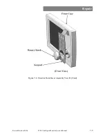
Page 53: ...Repair Revised October 2004 3800 Vital Signs Monitor Service Manual 7 9 Figure 7 8 Monitor Front Bezel Assembly View B Front...

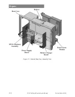
Page 54: ...Repair 7 10 3800 Vital Signs Monitor Service Manual Revised October 2004 Figure 7 9 Monitor Rear Case Assembly View...

Page 55: ...Repair Revised October 2004 3800 Vital Signs Monitor Service Manual 7 11 Figure 7 10 Input Panel Assembly View...

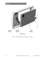
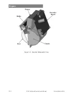
Page 56: ...Repair 7 12 3800 Vital Signs Monitor Service Manual Revised October 2004 Figure 7 11 Recorder Subassembly View...

Page 57: ...Repair Revised October 2004 3800 Vital Signs Monitor Service Manual 7 13 Figure 7 12 Input Panel Subassembly View...

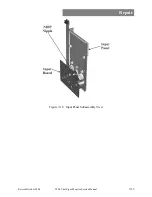
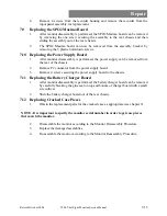
Page 58: ...hstand test should be performed if the monitor was disassembled see chapter 11 for details 7 7 Replacing the Display Before getting started please refer to the figure that shows the monitor front beze...

Page 59: ...be removed from the rear of the chassis 2 Remove P2 connector from the power supply board 3 Remove 4 screws securing the power supply board to the chassis 7 11 Replacing the Battery Charger Board 1 Af...

Page 60: ......

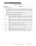
Page 61: ...nch 5 Lead Wires 40 inch Shielded IEC Color Coded 9261A ECG Snap 5 Lead Wires 40 inch Shielded IEC Color Coded UNSHIELDED ECG Cable and Lead Wires 9201 ECG Patient Cable 3 lead 10 foot safety 9331N Ne...

Page 62: ...Use SpO2 Sensors To activate the SET monitoring feature the monitor must be equipped with the Masimo SET technology 12 foot length 9289A Masimo Sensor Adapter Cable Adapter cable required for use with...

Page 63: ...Accessories Part Number Description AIR HOSE For use with the Escort M8TM Monitor 9010S Single Lumen NIBP Air Hose Quick disconnect fitting REUSABLE Single Lumen Infant to adult thigh For use with the...

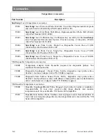
Page 64: ...S Probe Covers Single Use Disposable Covers Case of 10 000 Welch Allyn Part Number 05031 110 YSI Disposable Temperature Accessories 9200B Temperature Adapter Cable Reusable required for disposable pro...

Page 65: ...nting hardware 9401L Escort M8TM GCX Wall Mount This polymount bracket installs on any wall and permits the monitor to swivel allowing viewing from any angle and smoothly tilt from 0 to 28 degrees avo...

Page 66: ......

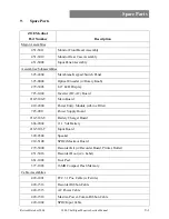
Page 67: ...isplay 725 1000 Inverter DC AC Board 210 5100 T Main Board 410 2000 Power Entry Module w Line Filter 725 0011 Power Supply Board 210 5103 T Battery Charger Board 666 2002 11 1 Vdc Battery 210 5101 T I...

Page 68: ...Spare Parts 9 2 3800 Vital Signs Monitor Service Manual Revised October 2004 420 1508 Inverter Control Cable ZOE Medical Part Number Description...

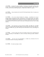
Page 69: ...ve eyewear 3 Prepare the enzymatic detergent according to the manufacturer s instructions and also the disinfectant solution in separate containers 4 Apply detergent to product using a soft cloth If m...

Page 70: ...m consuming power while the probe well is being cleaned Clean the inner and outer surfaces of the probe well by swabbing them with a cloth dampened with a mild detergent solution a 70 isopropyl alcoho...

Page 71: ...ter or cleaning solution Be careful to avoid getting cleaning liquids into connectors or the monitor If this occurs allow the unit to dry in warm air for 2 hours then check to make sure all monitoring...

Page 72: ......

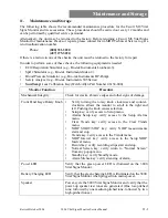
Page 73: ...mber 06138 000 Monitor Function Procedure Mechanical Integrity Check for cracks abrasive edges and other signs of damage Front Panel Keys Rotary Knob Verify turning the rotary knob clockwise and count...

Page 74: ...auge Inflate the cuff to 250 5 mmHg Do not allow system to remain pressurized and stable below 20 mmHg The monitor will remove this pressure as a zero offset and this will affect the validity of the c...

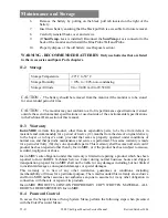
Page 75: ...S connector from the connection located in the center rear of the monitor 5 Remove the cover with the CE Mark as follows Hold the cover in place while removing the two screws from the top left and ri...

Page 76: ...product which has been reported to InvivoMDE s Technical Service Center during normal business hours and shipped transportation prepaid InvivoMDE shall not be liable for any damages including but not...

Page 77: ...Maintenance and Storage Revised October 2004 3800 Vital Signs Monitor Service Manual 11 5 Set Dial 1 to 49 Set Dial 2 to 48 Set Dial 3 to 46 Select OK...

Page 78: ......

Page 79: ...end of its useful life the Escort M8 Vital Signs Monitor should be properly disposed of as well In particular the Escort M8 Vital Signs Monitor contains a lithium coin battery an lithium ion battery p...

Page 80: ......

Page 81: ...0601 2 27 IEC 60601 2 30 IEC 60601 2 49 Patient Risk Current AAMI ES1 1993 Electromedical Apparatus with Isolated Patient Connection Meets the following limits Enclosure Risk Current 100 uA Patient ap...

Page 82: ...Standard CSA C22 2 No 601 1 M90 For indoor use only Attention Consult accompanying documents before using this device 05 2001 Manufacture date month year Type CF Equipment Defibrillation proof Antenn...

Page 83: ...Charging Method Battery is charged while monitor is connected to the AC mains supply Environmental Cooling Convection no fan Operating Temperature 59 to 104 F 15 to 40 C Storage Temperature 4 to 122...

Page 84: ...inusoidal ventricular fibrillation Notch Filter Frequency 50Hz 60Hz or Off Monitor Bandwidth 0 4Hz to 50Hz 3dB Dynamic Range AC 20 mV Dynamic Range DC 300 mV Electrode Impedance 2 5 Mohm at 10 Hz Defi...

Page 85: ...aturation of arterial hemoglobin Input Connector 7 pin Limo connector See Accessories for probe information SpO2 PR Resolution SpO2 1 O2 PR 1 bpm beat per minute Measurement Range SpO2 1 to 100 PR 25...

Page 86: ...mHg Diastolic 10 to 210 mmHg Mean 20 to 230 mmHg Measurement Accuracy Systolic Within 5 mmHg 8 mmHg Diastolic Within 5 mmHg 8 mmHg Mean Within 5 mmHg 8 mmHg Pulse Rate Range 30 to 240 bpm Pulse Rate A...

Reviews: