Operational manual for dynamic braking unit
-19-
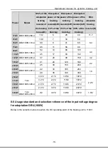
Power
Model
100% of
the
adaptation
braking
resistor of
the braking
torque(Ω)
Dissipated
power of the
braking
resistor(kW)
(10% of the
braking)
Dissipated
power of the
braking
resistor(kW)
(50% of the
braking)
Dissipated
power of the
braking
resistor(kW)
(80% of the
braking)
Mini
allowable
braking
resistor(Ω)
37kW
DBU100H-110-6
32.7
6
28
44
10.0
45kW
26.9
7
34
54
55kW
22.0
8
41
66
75kW
16.1
11
56
90
90kW
13.4
14
68
108
110kW
11.0
17
83
132
132kW
DBU100H-160-6
9.2
20
99
158
6.9
160kW
7.6
24
120
192
200kW
DBU100H-220-6
6.1
30
150
240
5.0
220kW
5.5
33
165
264
250kW
DBU100H-320-6
4.8
38
188
300
3.4
280kW
4.3
42
210
336
315kW
3.8
47
236
378
350kW
3.5
53
263
420
400kW DBU100H-400-6
3.0
60
300
480
2.8
500kW
Two
DBU100H-320-6
4.8*2
38*2
186*2
300*2
5.0*2
560kW
4.4*2
42*2
210*2
336*2
8.7 Selection of the braking resistors:
It is recommended to apply non-inductive resistance to reduce the inductance.
The protective devices for auto-partitioning during overheating are necessary.
The grounding fault is prohibited; otherwise the damage to the device and DBU may
occur.
The capacity of the braking resistor is the reference value and it can be modified
according to the inertial loads, braking frequency, braking voltage threshold. Please
consult with our company for more information.
Our company also has cement resistor and big power printing resistor and non inductive
Summary of Contents for DBU100H Series
Page 1: ...DBU100H Dynamic Braking Unit...
Page 27: ...201811 V1 6 66001 00143 I I...

