Goodrive18 series two-in-one VFD Communication
-126-
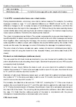
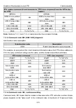
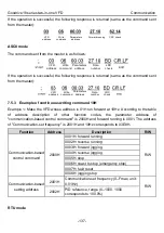
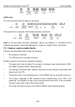
ASCII master command (from the master
to the VFD)
ASCII slave response (from the VFD to the
master)
LRC CHK Hi
‘1’
/
/
LRC CHK Lo
‘7’
/
/
END Hi
CR
/
/
END Lo
LF
/
/
7.4 Data address definition
This section describes the address definition of communication data. The addresses are used
for controlling the running, obtaining the status information, and setting function parameters of
the VFD.
7.4.1 Function code address format rules
The address of a function code consists of two bytes, with the MSB on the left and LSB on the
right. The MSB ranges from 00 to ffH, and the LSB also ranges from 00 to ffH. The MSB is the
hexadecimal form of the group number before the dot mark, and LSB is that of the number
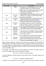
behind the dot mark. Take
as an example: The group number is 05, that is, the MSB of
the parameter address is the hexadecimal form of 05; and the number behind the dot mark is
05, that is, the LSB is the hexadecimal form of 05. Therefore, the function code address is
0505H in the hexadecimal form. For
, the parameter address is 0A01H.
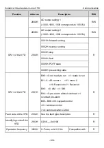
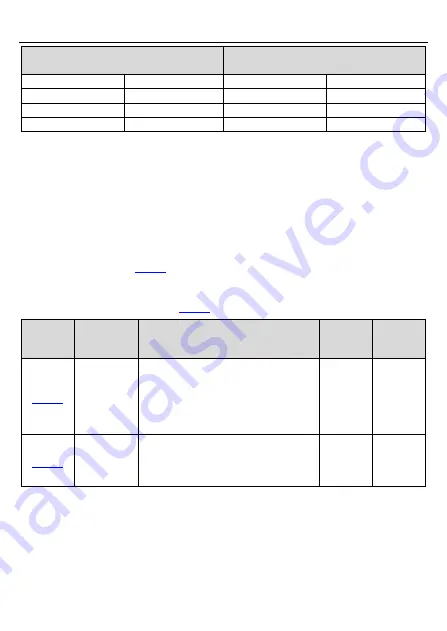
Function
code
Name
Detailed parameter description
Default
value
Modify
Simple PLC
means
0: Stop after running once.
1: Run at the final value after running
once.
2. Cycle running.
0
○
Simple PLC
memory
selection
0: Power loss without memory
1: Power loss with memory
0
○
Note:
• P29 group is the factory parameters which cannot be read or changed. Some parameters
cannot be changed when the VFD is in the running state and some parameters cannot be
changed in any state. The setting range, unit and related descriptions should be paid
attention to when modifying the function codes.
Summary of Contents for GD18-004-4-2
Page 1: ......


