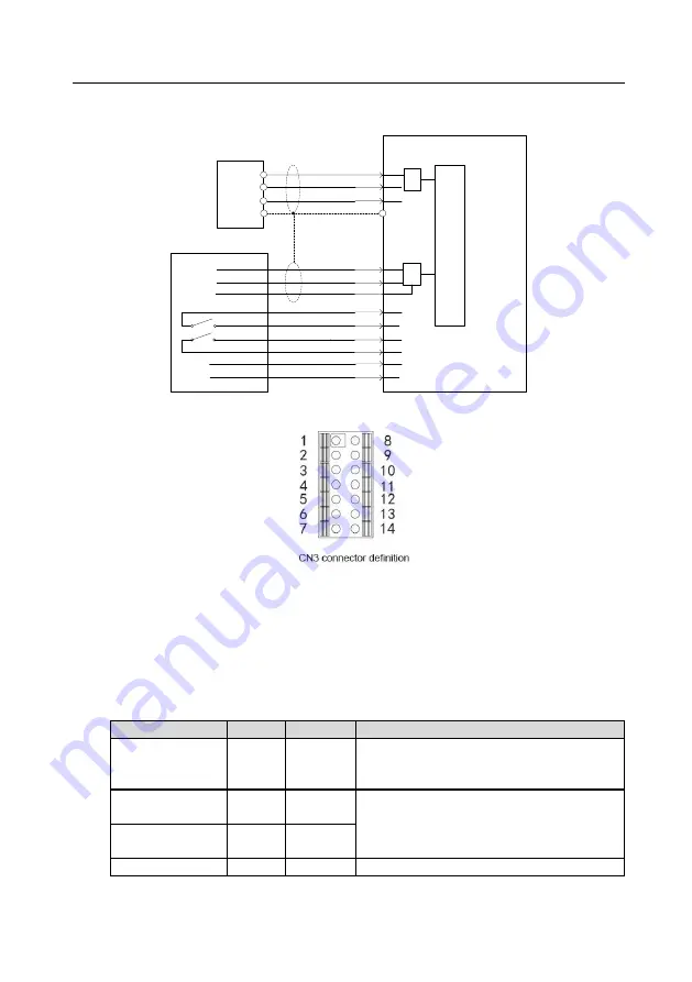
MH860 series hydraulic servo drive
Electrical connection
30
4.7.3 Typical control signal wiring examples
Servo drive
A/D
AIN3+
3
u
1
x
2
x
1
* / *
AGND
AGND
+15V
7
20
8
15V
Pressure sensor
S-ON
+24V
Output
Ground
Power
Green
Red
Black/Blue
10
19
ALM_RST
9
Enable drive
Fault reset
1
Flow reference 0-10V
AIN1+
AIN2+
2
4
u
1
x
2
x
1
* / *
Voltage reference 0-10V
PE
Alarm output
ALM+
17
ALM-
18
System controller
GND24V
CN5
4.8 CAN/RS485 connector terminal (CN3)
The drive carries two CAN communication interfaces and one RS485 communication
interface, which supports the standard Modbus RTU communication protocol. The RS485
communication end has been configured with a built-
in 1kΩ terminal resistor.
CAN communication port 1 supports the CANopen communication protocol and internally
connects to a 220Ω terminal resistor.
CAN communication port 2 is used to connect multiple drives in multi-pump parallel
connection system, also used as the CAN communication interface for INVT PC debugging
software SCM. It internally connects to a 220Ω terminal resistor.
Signal name
Symbol
Pin
Function
RS485
communication
interface
RS485_A
RS485_B
CN3-1, 8
CN3-2, 9
Semi-duplex. Supporting 9600bps, 19200bps,
38400 bps, and 57600bps (19200bps by default)
CAN communication
port 1
CAN1H
CAN1L
CN3-3, 10
CN3-4, 11
Standard CAN protocol signal, using the
optocoupler for isolation, supporting direct
access to CAN-BUS
CAN communication
port 2
CAN2H
CAN2L
CN3-5, 12
CN3-6, 13
Shield ground
PE
CN3-7, 14 Connecting to the housing


