background image

6

7

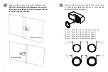
Optional. The lock is sized to fit a 22 mm – 23 mm hole. 
To install lock into larger hole (24 mm - 32 mm) use the 
appropriate spacer (included).

2

(0.95”)

24 mm

(1.10”)

28 mm

(1.02”)

26 mm

(1.18”)

30 mm

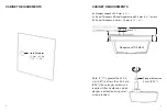
Determine if front panel is on right or left hand side. 

Note: The illustrations in this booklet are for right 
front panel orientation. For left front panel cabinet 
install in opposite direction.

1

Right Front Panel

Left Front Panel

22 mm ≤ hole size < 24 mm: No spacer required
24 mm ≤ hole size < 26 mm: 24 mm spacer
26 mm ≤ hole size < 28 mm: 26 mm spacer
28 mm ≤ hole size < 30 mm: 28 mm spacer
30 mm ≤ hole size < 32 mm: 30 mm spacer

Summary of Contents for PL203

Page 1: ...Plunger Lock III PL203 ...

Page 2: ...binet Specification Glass bypass panels with a thickness range of 5 8 mm 10 mm 0 23 0 4 System Components 1 Plunger Lock III PL203 2 IR2 Key PK4400 Setup in 4 easy steps 1 Gain access to front and back of front panel and mounting hole 2 Place Plunger Lock body into hole 3 Align back plate with lock from back side of panel 4 Attach plate to Plunger Lock body using 4 screws provided Caution Wear app...

Page 3: ...hickness Panel Gap must be 20 5 mm 0 81 or less Z Panel Thickness 5 8 mm 10 mm 0 23 0 4 Note If Y is greater than 20 5 mm 0 81 but less than 24 5 mm 0 96 then plunger extension is required Attach extension when plunger is extended using small screw provided Y X Z Plunger Extension 4 mm 0 15 3 mm 0 12 Plunger Lock TOP VIEW ...

Page 4: ...f front panel is on right or left hand side Note The illustrations in this booklet are for right front panel orientation For left front panel cabinet install in opposite direction 1 Right Front Panel Left Front Panel 22 mm hole size 24 mm No spacer required 24 mm hole size 26 mm 24 mm spacer 26 mm hole size 28 mm 26 mm spacer 28 mm hole size 30 mm 28 mm spacer 30 mm hole size 32 mm 30 mm spacer ...

Page 5: ...8 9 Rotate back plate until holes on back plate align and seat with screw holes on Plunger Lock 4 Back Plate Slide Plunger Lock through hole in front panel 3 ...

Page 6: ...10 11 Close cabinets before testing lock operation 6 Using screws provided alternate tightening screws to ensure proper fit Note 1 Phillips screwdriver with magnetic tip recommended 5 ...

Page 7: ...ainst lock push button and wait for beep before removing key Lock and unlock product several times to ensure proper operation IR2 Key must be charged and activated See IR2 Key instruction guide Hold until you get a confirmation beep Note If double buzz an error has occurred Unlock ensure panels are fully closed and try again Locked 7 BEEP Press Here ...

Page 8: ......

Page 9: ...InVue is a registered trademark of InVue Security Products SD0140 Rev0 10 08 12 www invuesecurity com Corporate Office North America 704 752 6513 888 55 INVUE Europe Middle East Africa 31 23 8900150 Asia Pacific 852 3127 6811 Latin America 52 55 9000 3957 ...

Reviews: