background image


46 


4.3.7.2


  Web-GUI   


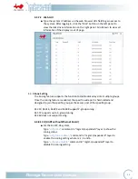
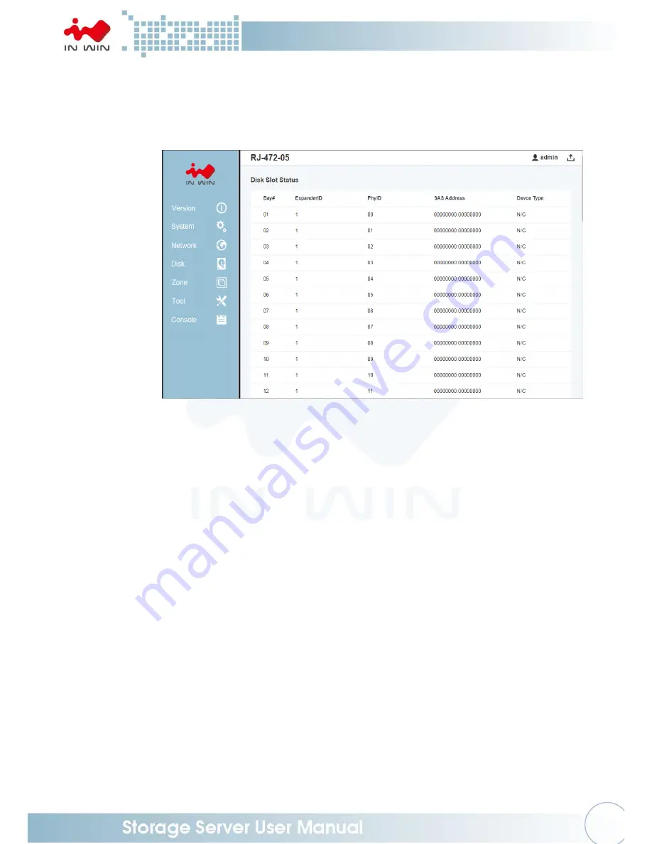
Type the system IP address on the web browser URL field to gain access to 

the system. After logging in, click the “Disk” button on the left panel to 

view the disk drives information on the right panel. Scroll down to view all 
information if the display is out of page.   


4.3.8


Zone Setting   

The Zoning feature supports the function to divide disk arrays into multiple groups. 
Once the zoning feature is enabled, the specific-wide port is hard-coded and 
designed to join the specific group as the access port of the specific group. 


RJ-212, RJ-316, RJ-224 and RJ-448 support 2-group zoning. 


RJ-472 supports up to 6-group zoning. 


RJ-460 does not support zoning. 


4.3.8.1


CLI (UART without Ethernet Board)   


For the RJ-472-05 system, 

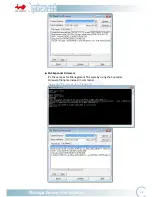
Type


“ucfg.zone”


command in “mgmt.s/expander0” layer to sh

ow the


zoning status.   
Type


“ucfg.zone enable

 n


command in “mgmt.s/expander0” layer to 

enable the zoning setting where n= 2, 3 and 6. 
Type 

“ucfg.zone disable”


command in “mgmt.s/expander0” layer to 

disable the zoning setting.   

Summary of Contents for IW-RJ472-05

Page 1: ...IW RJ472 05 User s Manual...

Page 2: ...Hard Drive 10 2 2 2 Removing a Hard Drive 11 2 3 Removing and Installing the Fan Module 12 2 3 1 Removing the Fan Module 12 2 3 2 Installing the Fan Module 13 2 4 Removing and Installing the PSU FAN...

Page 3: ...binet External Cable Management Arm Installation 27 3 Expander Board Introduction Host Disk 28 3 1 Expander Board Host 28 3 2 Expander Board Disk 29 4 User Interface Introduction 30 4 1 Overview 30 4...

Page 4: ...lated room and away from sources of heat including direct sunlight and radiators It should be kept away from sources of vibration or physical shock The space should be accommodated with a properly gro...

Page 5: ...umper carefully and plug the jumper to cover the jumper pins on the backplane Once you need to remove the jumper grip the jumper and carefully pull without squeezing CAUTION To avoid damage and mainta...

Page 6: ...ansion Port 6 x Mini SAS HD SFF 8644 for each 12G expander module Management Smart fan thermal monitor HDD monitor voltage monitor alarm warning SES Supports SES 2 SCSI Enclosure Service Maintenance S...

Page 7: ...4 1 Product Introduction 1 1 Box Contents...

Page 8: ...the IW RJ472 05 JBOD enclosure is a high density 4U rackmount storage chassis with 72 tool less bays dual hot swap SAS 12G expander modules six Mini SAS HD SFF 8644 for each 12G expander module six P...

Page 9: ...LED Blue Solid on Press the button to activate chassis identification 3 Status LED Red Solid on System maintenance PSU fan malfunction 4 Drives Status LEDs for Bays 1 72 Follow the table below Drive...

Page 10: ...Module 3 Fan Module 1 PSU FAN Module 10 Secondary expander Module 4 Fan Module 2 PSU FAN Module 11 Power Module Handle 5 Fan Module 3 PSU FAN Module 12 Power Switch 6 Fan Module 4 PSU FAN Module 13 PS...

Page 11: ...al Downlink Connect to cascading JBOD 4 Expander Module Status LED Heartbeat 5 ID LED Button Press the button to activate chassis identification 6 Expander Serial Port RS 232 RS 232 Support 7 Network...

Page 12: ...em from HDD overheating Step 1 Loosen the thumbscrews of the top cover Step 2 Pull the thumbscrews to release the top cover Slide and tilt the cover upward from the front and lift to remove Step 1 Ste...

Page 13: ...over and pull it outward as a handle Step 2 Pull up the tray until it clicks Step 3 Fully insert the HDD into the tray from the correct disk port orientation Step 4 Align the HDD screw holes and plug...

Page 14: ...the arrow on the tray Open the disk tray cover and pull it outward as a handle Step2 Pull up the tray until it clicks Step3 Pull the hard drive out carefully Step4 Lower the disk tray back Release th...

Page 15: ...in fan modules that support hot swappable and redundant features which is easy to maintain with the tool less design 2 3 1 Removing the Fan Module Step 1 Loosen the thumbscrew of the fan module Step 2...

Page 16: ...and three fan modules With this function the system is capable of still functioning if one of the modules fail To replace it the user only needs to release the failed module then insert a functional m...

Page 17: ...Step 1 Step 2 2 4 2 Installing the PSU FAN Module Step 1 Push the PSU FAN module cage back until it clicks Step 2 Tighten the thumbscrew to secure the cage Step 1 Step 2 Push Pull Push PSU Fan PSU Fa...

Page 18: ...to monitor and maintain the system Also the redundant module can minimize downtime should any on the expanders fail 2 5 1 Removing the Host Expander Module Step 1 Loosen the thumbscrew of the host ex...

Page 19: ...o prevent the system from HDD overheating Step 1 Open the top cover of the chassis Please refer to 2 1 1 Step 2 Remove the cable from the disk expander module Step 3 Loosen the thumbscrew of the modul...

Page 20: ...tep 1 Place the disk expander module into the cage until it clicks Step 2 Put the thumbscrew into position and tighten the thumbscrew Step 3 Connect the cable to the disk expander module Step 4 Close...

Page 21: ...18 Step 2 Step 3 Connects the Cables Connects the Cables...

Page 22: ...the stop Release the blue slide tab to unlock Step 2 Continue pulling the inner rail until the second stops Release the white slide tab to remove the inner rail Step 3 Pull the latch on the middle ra...

Page 23: ...l the rail bracket pins that go into the front post holes on the rack until they click Step 5 The other side of the rail is symmetrical repeat the installation steps 1 4 Step 6 Once you would like to...

Page 24: ...position release the blue slide tab again to continue Step 6 Push the chassis into position on the rack completely Make sure that the front end of the chassis is aligned with the edge of the rack to...

Page 25: ...nal cable management arms 2 7 2 Mounting Bracket Installation Step 1 Align the quick release extension bracket G 2 1 to the cabinet mounting bracket G 1 screw holes tighten with two round head screws...

Page 26: ...ten it down Step 2 Insert the latch of the cable management stop bracket D into the quick release extension bracket G 2 1 on the cabinet mounting bracket G 1 Refer to 2 7 2 Step 1 When removing press...

Page 27: ...t G 1 Refer to 2 7 2 Step 2 When removing press the blue dot to pull out Support Arm C 2 Step 1 Place the support arm C 2 hexagon head screw down to the middle hollow of the support arm C 1 and fasten...

Page 28: ...head screws K Step 4 Secure the swivel pin E to the chassis mounting bracket F 2 7 4 Cable Management Arm Installation Step 1 Insert the quick release latch B 1 into the right of the cable management...

Page 29: ...h B 2 into the other side of the cable management arm A When removing press the blue dot to pull out Step 3 Insert the other side of the quick release latch B 2 into the chassis mount bracket F When r...

Page 30: ...osition Step 3 Tighten the flat head screw I to secure the mounting bracket G 1 to the cabinet For more detailed dynamic installation instructions see the RJ472 Rail CMA Assembly Live Video File Link...

Page 31: ...S6 Expansion External Downlink MINI SAS HD Connector LED1 LED6 PHY LINK LED LED7 Status LED CN1 Programming Factory only SW1 ID SW LED SW2 System Reset Factory only SW3 Flash burn in test Factory only...

Page 32: ...bug Mode JD3 Console Smart Mode JC1 MB Fan Control JC2 PMBUS JC3 Front Panel Signal Connector EFN1 Expander Fan connector LED11 12 13 LED11 13 JS1 JS3 PHY LED LED01 Expander Heart Beat LED JS1 JS3 JS1...

Page 33: ...uctions of frequent use function Please refer to the table of contents to find the topics you are interested in 4 2 Key Features Reliable High Data Rate Support up to 12Gbps SAS 12Gbps support and SAT...

Page 34: ...ature enables single JBOD to serve multiple hosts Cascading There are cascading ports on the Expander for cascading another JBOD system to expand disk space when more space is required 4 3 Software Ma...

Page 35: ...o manage the system through terminal console applications such as Tera Term Putty etc Users need to prepare a DB9 RS 232 adapter on host and connect to a serial cable shipped along with the system to...

Page 36: ...can manage the network setting such as configuring the IP address and enabling disabling services The list command to displays all the Ethernet layer commands the system supports The help command list...

Page 37: ...for jumping back to the network management layer from expander management layer The or help displays the CLI commands for the SAS Expander Type command to display the current status of the command Ty...

Page 38: ...the settings to meet the network environment For security reasons we strongly recommend users to change the password immediately before the system is put online Note 4 3 3 1 Telnet The Telnet service...

Page 39: ...led by default It provides the same level of CLI commands as it is through serial console or Telnet session SSH provides a secure connection between host and the JBOD system It is enabled by default o...

Page 40: ...37...
Page 41: ...is the easiest way to manage the JBOD system It is enabled by default on this system Users can simply open the web browser and give the JBOD management IP address in the URL address field to start man...

Page 42: ...dded with a SNMP agent The InWin JBOD system s management module is implemented by a SNMP agent with v1 and v2c support Users need to configure the same read and write community string in the JBOD sys...

Page 43: ...onfigure via Web SNMP Manager Any SNMP Managers can be used to manage the system by properly configuring the system settings including IP address read community string and write community string to ma...

Page 44: ...irmware version through various ways with CLI commands Web GUI and SNMP 4 3 4 1 CLI UART Telnet and SSH Type the version command on mgmt s Layer to display all the version information including Ethern...

Page 45: ...ress on Web Browser URL address field to gain access to the system After logging in click Version on the left pane to view the system version information on the right pane Scroll down to view all info...

Page 46: ...their status Please note that the Expander temperature sensors Exp Die is the silicon core temperature and the temperature sensors BPx Sensor x are on the backplanes There are mechanisms communicating...

Page 47: ...commands on mgmt s layer such as ipaddr gateway netmask etc to view and configure the settings respectively Please be sure to apply the save command so the settings are saved for the next system rebo...

Page 48: ...show the disk drives status on the system including Bay id Phy id SAS Address Link speed and current status 4 3 7 1 CLI UART Telnet and SSH Type the phyinfox s command on mgmt s expander0 layer to dis...

Page 49: ...ning feature is enabled the specific wide port is hard coded and designed to join the specific group as the access port of the specific group RJ 212 RJ 316 RJ 224 and RJ 448 support 2 group zoning RJ...

Page 50: ...the right panel of the page Click Enable to enable zoning and click Disable to disable zoning After configuration is selected click Apply to reset the Expander to take effect Zoning configuration wit...

Page 51: ...SAS Expander MFG CFG file There are a couple of ways to upgrade the system firmware according to the HW configurations Please note that the upgraded firmware won t take effect until a system reboot No...

Page 52: ...iently all Expanders including Bridge Expander and internal expanders they are sharing the same firmware and MFG file can be upgraded at the same time when upgrade command is applied and committed To...

Page 53: ...50 SAS Expander Firmware It s the same as for Management firmware by using the Expander Firmware filename instead in command upgrade tftp_server_ip filename...

Page 54: ...ys Just simply select the firmware by file browser and click Apply to start All the firmware including Network Management firmware SAS Expander firmware and MFG CFG file apply the same way to upgrade...

Page 55: ...file browser and click Open to commit The firmware can be management firmware SAS Expander firmware or SAS Expander MFG CFG file The system would intelligently detect the firmware type and upgrade to...

Page 56: ...53 Web would direct to a page telling the firmware is upgrading After upgrade is done Web will direct to the Login page A system reboot is require to take effect...

Page 57: ...Web Console Login into Web GUI then click Console on the left panel Then on the right panel select the SAS expander that you would like to apply the command to and fill the command to the rightest sq...

Page 58: ...assword reboot reboot management board save save configuration to NVRAM service display or set service Telnet SSH WEB SNMP upgrade upgrade management board or expander software useradd add new user ac...

Page 59: ...main recv sas_addr If sas_addr set then fetch the remote expander s current clock and output the result If sas_addr not specified then get and output the current clock for all expanders in the domain...

Page 60: ...POST info showpost Show MFG Revision showmfg Show firmware revision rev 5 Compatibility Lists To reach the best performance and avoid system failure InWin strongly recommends users to choose the comp...

Reviews: