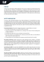
background image


PREFACE 

Thank you for choosing the InWin IW-RS110-07. This manual is written for system technicians who 
are responsible for installation, troubleshooting, managing and repairing this server chassis. This 
document  provides  an  overview  of  all  the  features  of  the  chassis,  a  list  of  accessories  or  other 
components you may need to finish the installation, troubleshooting methods and instructions on 
adding and removing components in the InWin IW-RS110-07. For the latest version of this manual, 
you may visit InWin’s server website. 


SAFETY INFORMATION 

To ensure a safe and smooth operation of your InWin IW-RS110-07, it is essential that you choose 
an appropriate location for the system, provide an appropriate operating environment and supply 
an adequate amount of power for all components of the system. As you plan for installation, follow 
the guidelines below to ensure that the system and its environment are safely and appropriately 
positioned for efficient operation and service. Your system should be installed and serviced only by 
a qualified technician. 
 

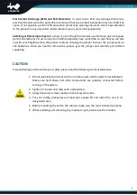
Environment Selection:

 The system is designed to operate in a typical office environment:   


The location should be clean, dry and free of airborne particles.   


It should be placed in a well-ventilated room, and away from sources of heat including direct 
sunlight and radiators.   


It should be kept away from sources of vibration or physical shock.   


The space should be accommodated with a properly grounded wall outlet, and with sufficient 
space to access the power supply cords.   


The operating environment temperature should be around 0°C to 40°C (32°F to 104°F). 


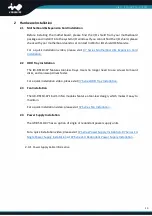
Heed  Safety  Instructions:

  Before  working  with  InWin  IPC/storage  server  products,  we  strongly 

recommend you use this guide as a reference and follow the safety instructions. The instructions in 
this manual will help you ensure and maintain compliance with existing product certifications and 
approvals. Follow the described, regulated components mentioned in this manual. Use of non-UL 
listing  products  or  other  regulators  may  not  comply  with  product  regulations  in  the  region(s)  in 
which the product is sold.   
 

System Power On/Off:

 The power button DOES NOT totally turn off the system AC power. To remove 

the power of the system, you must unplug the AC power cord from the outlet or the system’s power 
supply units. Make sure the power cord is unplugged before you open the chassis, add or remove 
any components.   
 

Hazardous Conditions, Devices and Cables:

 Hazardous electrical conditions can be present on/in 

power supply units and their cables. Disconnect the power cord and any other devices attached to 
the  server  before  opening  the  case.  Failing  to  follow  safety  procedures  will  increase  the  risk  of 
personal injury or equipment damage.   

Summary of Contents for IW-RS110-07

Page 1: ...IW IW IW IW RS110 RS110 RS110 RS110 07 07 07 07 User Manual User Manual User Manual User Manual ...

Page 2: ...0 2 1 Motherboard Expansion Card Installation 10 2 2 HDD Tray Installation 10 2 3 Fan Installation 10 2 4 Power Supply Installation 10 2 4 1 Power Supply Cable Information 10 2 5 Connecting Cables 13 2 5 1 Connecting Backplane Through SAS Connectors 13 2 5 2 Connecting LED Cable Front Control Panel and Front USB I O Ports 13 2 6 Installing the Slide Rail 14 2 6 1 Identifying the Slide Rail 14 2 6 ...

Page 3: ...4 Compatibility Lists 18 5 Q A 19 6 Technical Support 20 ...

Page 4: ... from sources of heat including direct sunlight and radiators It should be kept away from sources of vibration or physical shock The space should be accommodated with a properly grounded wall outlet and with sufficient space to access the power supply cords The operating environment temperature should be around 0 C to 40 C 32 F to 104 F Heed Safety Instructions Before working with InWin IPC storag...

Page 5: ...er carefully and plug the jumper to cover the jumper pins on the backplane Once you need to remove the jumper grip the jumper and carefully pull without squeezing CAUTION To avoid damage and maintain your safety please read the following terms listed below 1 Do not populate hard drives and turn on the power until the system has stabilized Make sure hard drives and other components are properly con...

Page 6: ...r SAS protocol SSD 8639 x 10 for NVMe SAS SATA device Cooling Fan 40 x 56mm PWM easy swap fans x 6 21500RPM modular design with anti vibration Expansion Slot Full height PCIe slot x 1 via riser card Material Material SGCC Thickness 1 0mm Rail Kit Supports 28 tool less ball bearing slide rails Product Dimensions D x W x H Chassis Only 676 5 x 438 x 43 4mm 26 6 x 17 2 x 1 7 Packaging Dimensions D x ...

Page 7: ...ace Slimline internal SFF 8654 x 10 for PCIe protocol 8643 x 3 for SAS protocol HDD Interface 8639 x 10 for NVMe SAS SATA device Backplane 2 Oculink Backplane Dimensions W x H 400mm x 37 3mm Backplane Type Passive Host Interface Oculink internal SFF 8611 x 10 for PCIe protocol 8643 x 3 for SAS protocol HDD Interface 8639 x 10 for NVMe SAS SATA device ...

Page 8: ...5 1 Product Introduction 1 1 Box Contents When you open the IW RS110 07 box the contents should include following ...

Page 9: ...Standoffs x 2 3 Power LED 3 pin to 2 pin Adapter x 1 8 Backplane Jumper x 1 4 Cable Ties and Mounts x 5 9 Redundant Power Supply Accessories a Screws x 6 b Mounting Brackets x 2 5 Motherboard Screws x 11 10 Single Power Supply Accessories a Countersunk Flat Head Screws x 2 b Oval Head Screws x 4 c Mounting Bracket x 1 ...

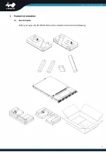
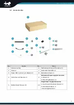
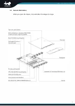
Page 10: ...7 1 3 General Information When you open the chassis it should reflect the diagram s image ...

Page 11: ... the button to activate user defined function 3 Power On Off Button with LED Green Solid on System is powered on N A Off System is off 4 Chassis ID Button with LED Blue Solid on Press the button to activate system identification 5 Hard Disk LED Amber Blinking System HDD accessing 6 System Fail LED Amber Solid on System Status Green Solid on System Status 7 LAN LED LAN1 LAN2 Green Blink Link betwee...

Page 12: ...ence InWin s compatibility list to select the compatible models 2 System I O Depends on M B Specifications InWin offers a customized service for 1U I O shield For more information please contact InWin s sales reps 3 Full Height PCIe Slot x 1 The slot supports standard high profile cards The bracket should be removed before using ...

Page 13: ...ol less trays Users no longer need to use screws to mount disks and can swap drives faster For a quick installation video please visit 07 Series HDD Tray Installation 2 3 Fan Installation The IW RS110 07 s built in fan modules feature a tool less design which makes it easy to maintain For a quick installation video please visit 07 Series Fan Installation 2 4 Power Supply Installation The IW RS110 ...

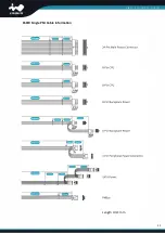
Page 14: ...11 650W Single PSU Cable Information Length Unit mm ...

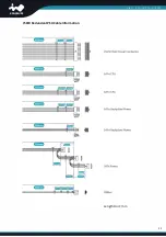
Page 15: ...12 750W Redundant PSU Cable Information Length Unit mm ...

Page 16: ...gh SAS Connectors The InWin IW RS110 07 needs the SAS cable to connect to the backplane and your motherboard or RAID controller InWin provides verified SAS cables for installation please contact InWin local partners and sales to get more information 2 5 2 Connecting LED Cable Front Control Panel and Front USB I O Ports As 1 2 1 describes the InWin IW RS110 07 has a built in front control panel and...

Page 17: ... rail package and follow the instructions to mount the rail onto your cabinet or chassis rack 2 6 2 Installing the Slide Rail Step 1 Release the inner rail from the slide No Connector Name Color Front I O Indication CN2 ID LED Red Black Chassis ID Button with LED CN3 System LED Yellow Green System Fail LED CN4 ID Switch Green Black Chassis ID Button with LED CN5 Power LED Red Black Power ON OFF Bu...

Page 18: ...the arrows show Step 3 Install the outer rails and the brackets onto the rack 2 6 3 Mounting the chassis onto the cabinet Step 1 Make sure the ball bearing retainer is at the forefront Step 2 Insert the inner rail to the outer rail which has already locked up on the cabinet ...

Page 19: ...16 Step 3 Mount the inner rail onto the chassis by the direction which the arrows show on the image Step 4 Tighten the thumb screws to secure the chassis ...

Page 20: ...r Please reference the backplane user guide to complete the installation The download link is at the download section of each product Please visit the InWin website ipc in win com Oculink Backplane Top Side Bottom Side Slimline Backplane Top Side Bottom Side ...

Page 21: ...2 Connect to fan modules The backplane supports up to 12 fan modules NVME1 NVME10 NVMe interfaces connect to NVMe HBA 4 Compatibility Lists To reach the best performance and avoid system failure InWin strongly recommends customers to choose the components from InWin s compatibility list All the components are tested in InWin s lab and assured the components are compatible with InWin s chassis You ...

Page 22: ...and NVMe SSD connections can be attached to the InWin IW RS110 07 We recommend customers refer to InWin s compatibility list to confirm if the SSDs are listed or please contact InWin s sales reps for better reference e If I don t need the front cover can I have the standard handle A The InWin IW RS110 07 supports both the standard handle and the bezel handle If you would like your chassis with a s...

Page 23: ...that you can easily buy from many vendors You can buy the verified cable from InWin to eliminate compatibility issues 6 Technical Support If you need help with installation or troubleshooting you can contact your local InWin sales reps or send an e mail to InWin s local contacts for technical assistance ...

Reviews: