background image

13

The IW-RS216-07 is a rackmount model, which supports EIA-RS310D standard cabinets and chassis 
racks. InWin provides standard slide rails to allow users to mount the chassis onto the cabinets.

2.6  Installing the Slide Rail

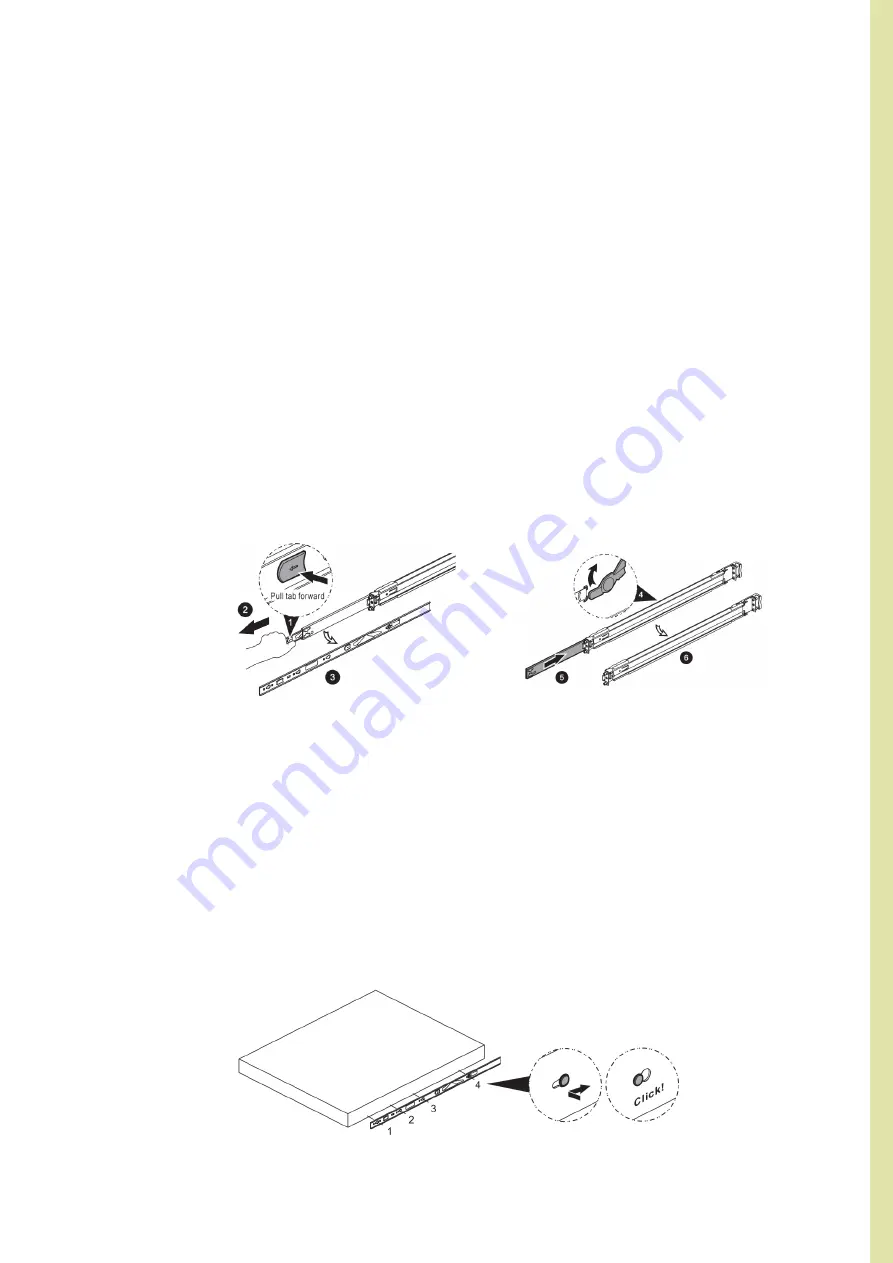
Step 1 - 2

Step 1 - 2

Step 3

The slide rail by your order might be different. You can reference the quick installation guide inside the 
slide rail package and follow the instructions to mount the rail onto your cabinet or chassis rack.

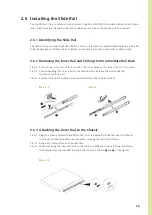
Pull out the inner rail until it reaches the stop. Release the blue slide tab to unlock. 
Continue pulling the inner rail until the second stops. Release the white slide tab 
to remove the inner rail.
Pull the latch on the middle rail upward and retract the middle rail back.

Align the chassis sidewall standoffs to the inner rail keyholes. Slide the inner rail toward 
the front until the standoffs snap into place, securing the rail to the chassis.
Repeat the same action on the other side.
When removing the inner rail: Pull up the latch and slide the inner rail forward. Remove 
the keyhole from the standoff to detach the inner rail. (Action 

and 

 in the figure)

2.6.1  Identifying the Slide Rail

2.6.2  Removing the Inner Rail and Sliding the Intermediate Rail Back

2.6.3  Attaching the Inner Rail to the Chassis

Step 1: 

Step 2: 
Step 3: 

Step 1: 
Step 2:
 
Step 3: 

Summary of Contents for IW-RS216-07

Page 1: ...2U NVMe Hybrid Storage Server User Manual IW RS216 07 ...

Page 2: ... typical office environment The location should be clean dry and free of airborne particles It should be placed in a well ventilated room and away from sources of heat including direct sunlight and radiators It should be kept away from sources of vibration or physical shock The space should be accommodated with a properly grounded wall outlet and with sufficient space to access the power supply co...

Page 3: ...to close open or bypass part of an electronic circuit Jumpers on InWin backplanes have a small tab on top that you can pick up with your fingertips Grip the jumper carefully and plug the jumper to cover the jumper pins on the backplane Once you need to remove the jumper grip the jumper and carefully pull without squeezing CAUTION To avoid damage and maintain your safety please read the following t...

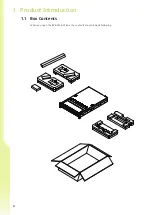
Page 4: ...4 When you open the IW RS216 07 box the contents should include following 1 1 Box Contents 1 Product Introduction ...

Page 5: ...ories Box No Item 1 Hexagon Head Screws x 12 Motherboard Stand off Sockets x 12 2 2 5 HDD Screws x 24 3 Power LED 3 pin to 2 pin Adapter x 1 No Item 4 Backplane Jumper x 2 5 Cables Ties and Mounts x 5 6 HDD Tray Mark Label x 1 ...

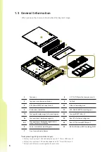
Page 6: ... cage kits mounting area 5a Top layer type 1 backplane cage kits 5b Top layer type 2 backplane cage kits and metal frames for installation 6 Server rack cabinet mounting ears 7 Front controls and indicator 6 When you open the chassis it should reflect the diagram s image 1 3 General Information 1 1 2 3 4 7 or 8 6 6 5 5a 5b 13 14 15 12 11 10 9 5a 1pc top layer type 1 OCuLink backplane and 2 5 15mm ...

Page 7: ... Power On Off Button with LED Green Solid on System is powered on N A Off System is off 4 Chassis ID Button with LED Blue Solid on Press the button to activate system identification 5 Hard Disk LED Amber Blinking System HDD accessing 6 System Fail LED Amber Solid on System Status Green Solid on System Status 7 LAN LED From top to bottom ranked LAN1 LAN4 Green Blinking Link between system and netwo...

Page 8: ...S disk backup module optional which supports two 2 5 12G SSDs and features hot swap function 4 System I O Depends on M B Specifications The I O shield should come with the motherboard or is provided by motherboard vendors 5 Low profile PCIe slots x 7 The slots support low profile cards The bracket should be removed before using 8 1 3 2 Rear Panel Configuration ...

Page 9: ... to mount disks and can swap drives faster For a quick installation video please visit 07 Series HDD Tray Installation 2 2 HDD Tray Installation The IW RS216 07 s built in fan modules feature a tool less design which makes it easy to maintain For a quick installation video please visit 07 Series Fan Installation 2 3 Fan Installation The IW RS216 07 has a built in redundant power supply unit With t...

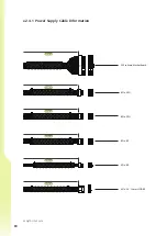
Page 10: ...10 2 4 1 Power Supply Cable Information Length Unit mm 24 Pin Main Motherboard 340mm 8 Pin CPU 250mm 8 Pin CPU 380mm 8 Pin BP 450mm 6 Pin BP 430mm 4 Pin 2 5 15mm HDD BP 280mm ...

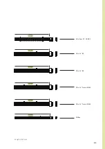
Page 11: ...11 Length Unit mm PMBUS PMBus 350mm 4 Pin Rear 2 5 HDD BP 300mm 5 Pin 3 5 BP 290mm 5 Pin 3 5 BP 290mm 5 Pin 2 5 7mm HDD BP 520mm 5 Pin 2 5 7mm HDD BP 770mm ...

Page 12: ...LED ID LED RED BLACK Chassis ID Button with LED CN3 SYSTEM LED SYS LED RED BLACK System Fail LED CN4 ID Switch ID SW RED BLACK Chassis ID Button with LED CN5 Power LED PW LED RED BLACK Power ON OFF Button with LED CN6 LAN 1 LED LAN1 LED RED BLACK LAN LED CN7 HDD LED HDD LED RED BLACK HDD Active LED CN8 Power Switch PW SW RED BLACK Power ON OFF Button with LED CN9 Reset Switch RESET SW RED BLACK Sy...

Page 13: ...nue pulling the inner rail until the second stops Release the white slide tab to remove the inner rail Pull the latch on the middle rail upward and retract the middle rail back Align the chassis sidewall standoffs to the inner rail keyholes Slide the inner rail toward the front until the standoffs snap into place securing the rail to the chassis Repeat the same action on the other side When removi...

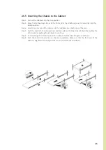
Page 14: ...Hang the front hooks of the outer rail at the front of the rack post holes Pull the rail bracket pins that go into the front post holes on the rack until they click The other side is the same process Repeat the installation steps 1 4 Once you would like to detach the bracket pull outward on the front and the rear hooks of the outer rail to release the bracket Repeat the same action to the other si...

Page 15: ...is to the stop position and then release the blue slide tab by either pulling the tab forward or pushing the tab back to continue Until reaching the second stop position release the blue slide tab again to continue Push the chassis into position on the rack completely Make sure that the front end of the chassis is aligned with the edge of the rack to complete the installation Step 1 Step 2 Step 3 ...

Page 16: ...NVMe SSD through OCuLink x 12 or 16 connectors The backplane varies by order Please reference the backplane user guide to complete the installation The download link is at the download section of each product Please visit the InWin website ipc in win com Top Layer Type 1 2 5 15mm x 2 SSDs The top layer type 1 OCuLink backplane has three OCuLink connectors Two of conectors are for U 2 NVMe transfer...

Page 17: ... the OCuLink connectors is only used for SAS SATA data transfer rates If there are no OCuLink connectors on MB HBA Raid controller card cable SFF 8611 can be replaced with SFF 8611 to SFF 8643 Please refer to the backplane user guide for more information For a quick installation video please visit 07 Series Oculink Backplane Connection For Mini SAS HD connector please use the SFF 8643 cable to con...

Page 18: ...S Communication Connector 4 Compatibility Lists 5 Technical Support To reach the best performance and avoid system failure InWin strongly recommends customers to choose the components from InWin s compatibility list All the components are tested in InWin s lab and assured the components are compatible with InWin s chassis You can download the latest updated device compatibility list from InWin s w...

Page 19: ...19 Copyright In Win Development Inc All Rights Reserved ...

Reviews: