MatchBox® series | User Manual
17
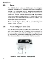
Viewing left-to-right, the pins are dedicated for: first pin is for VCC, next
two are UART bus interface pins Tx and Rx, then follows a multifunctional
programmable pin for TTL modulation or fan speed control. An empty slot
is used as a key, ensuring that the female pinhead connector will not be
polarizing in a wrong orientation or position. The fifth pin works as a
ground. The ground pin is soldered into the enclosure of the laser, thus
complete laser body is grounded.
2.7:
Specifications
The MatchBox series includes a variety of lasers featuring different
wavelength and power ratings. The actual specifications of a laser are
provided in a test report accompanying a laser, which is sold to the
customer. General specifications for all laser models can be found at
www.integratedoptics.com
, you can scan the QR code below for a quick
access to our website:
2.8:
Mechanical Design
The laser sources within the MatchBox series employ a single-box
design, which means that all optics, power electronics and thermal
management components are arranged inside a single enclosure.
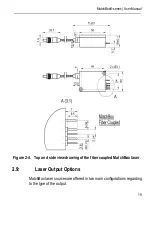
The overall dimensions of the laser are 30 x 50 x 18 mm
3
(Width x Depth
x Height), not taking into account the connecting pins, which are used for
connecting the laser to a power source and control interface. The pins
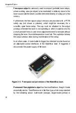
extend approx. 10 mm from the back of the laser. Different output options,
such as free-space output with or without a mechanical shutter,
Summary of Contents for MatchBox Series
Page 1: ...Version 2 5 October 2020 Continuous Wave laser...
Page 2: ......
Page 4: ...Integrated Optics 2...
Page 12: ...Integrated Optics 10...
Page 32: ...Integrated Optics 30...
Page 58: ...Integrated Optics 56...
Page 68: ...Integrated Optics 66...
Page 71: ...MatchBox series User Manual 69...
Page 72: ...Integrated Optics 70...


