background image

MatchBox® series | User Manual

1

INTRODUCTION

As the title hints, MatchBox® products are ultra-compact, single-unit laser
sources with overall dimensions comparable to a regular matchbox
(30x50x18 mm

3

), connector pins not included.

The MatchBox® series include a range of continuous wave laser sources,
featuring wide range of wavelength, output power, output type and line-
width options.

The series is composed of solid state (DPSS) lasers, passive Q-Switch
short-pulse lasers, multi-wavelength lasers based on classical dichroic
combining, as well as direct laser diode (LD) lasers. Despite the different
technical implementation, physical and electrical properties, usability and
connectivity are almost identical throughout the series, representing our
commitment to perfect user experience and faster time to market for our
customers.

Please take your time to read this instruction manual which provides
essential information about the usage of the continuous wave single-
wavelength lasers. We have also included various hints and tips that will
help you to get the most out of a certain laser source.

Summary of Contents for MatchBox Series

Page 1: ...Version 2 5 October 2020 Continuous Wave laser...

Page 2: ......

Page 3: ...h short pulse lasers multi wavelength lasers based on classical dichroic combining as well as direct laser diode LD lasers Despite the different technical implementation physical and electrical proper...

Page 4: ...Integrated Optics 2...

Page 5: ...12 2 3 Thermal Management 12 2 4 Power Supply 13 2 5 Cables 16 2 6 Power and Signal Connections 16 2 7 Specifications 17 2 8 Mechanical Design 17 2 9 Laser Output Options 19 2 10 Operating Environment...

Page 6: ...4 6 Communication Command Table 46 4 7 Communication with Multiple Lasers in a Bus 50 4 8 TTL Modulation 52 4 9 Attaching Control Interfaces 54 5 ACCESSORIES 55 6 TROUBLESHOOTING Q A 57 6 1 Frequently...

Page 7: ...ated to optical laser radiation and alerts the operator to the danger of exposure to hazardous visible or invisible laser radiation This symbol is a warning sign It marks safety precautions related to...

Page 8: ...hat is why the operator should always obey the safety measures given below The laser body of MatchBox is connected to the ground this means that all internal electronics share the same ground of the l...

Page 9: ...armful if observed at a distance of 1 m 3 ft or larger The use of eye protection when operating a MatchBox laser is necessary if at any circumstances the laser beam could be exposed to an eye directly...

Page 10: ...hields or filters to get rid of unnecessary reflections and scattering User must never wear any kind of jewellery or watches while using the laser system to avoid any laser beam reflections from those...

Page 11: ...t necessary safety means OEM type products are designed for installation into Class 1 enclosures However by adding accessories like beam shutter and key switch CDRH compliance is reached The CDRH Acce...

Page 12: ...Integrated Optics 10...

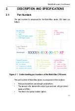
Page 13: ...x series CW lasers as follows Figure 2 1 Understanding part numbers of the MatchBox CW lasers The part number of MatchBox lasers is composed of five sections First section defines wavelength and platf...

Page 14: ...lasers Depending on model one or two thermo electric coolers TEC are equipped inside the enclosure for thermal management of a pump laser diode and associated optics Thermal stabilization of all criti...

Page 15: ...er in place of previously installed laser of other brands However adapter plates need to be attached to heatsinks having sufficiently low thermal resistance For efficient cooling make sure that there...

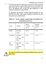
Page 16: ...eeds maximum current of 0 3 Amps and typical of 0 2 Amps To power MatchBox CW lasers with power delivery PD type power supplies Integrated Optics UAB recommend using a Break out Box further BoB The Bo...

Page 17: ...ics of power supply requirements for your MatchBox laser better power supply requirements regarding laser type during start up are depicted below The values in the table are not absolute for all laser...

Page 18: ...cables for power delivery and Break out Boxes are shipped with USB A to USB micro cables for data communication Please contact Integrated Optics UAB for a customized physical interface for data and po...

Page 19: ...al specifications of a laser are provided in a test report accompanying a laser which is sold to the customer General specifications for all laser models can be found at www integratedoptics com you c...

Page 20: ...Integrated Optics 18 permanently fixed fibers have different arrangements on the front facet of the laser Figure 2 3 Top and side view drawing of the MatchBox free space laser...

Page 21: ...es User Manual 19 Figure 2 4 Top and side view drawing of the fiber coupled MatchBox laser 2 9 Laser Output Options MatchBox laser sources are offered in two main configurations regarding to the type...

Page 22: ...en it could be shut for a short period of time in case minor adjustments need to be made without stopping the laser thus stable operation is not lost The cap helps to keep the output window clean duri...

Page 23: ...rd fiber pigtailed lasers do not have auto start enabled If one enables the auto start function please make sure the metal cap is removed from fiber tip before operating the laser If the cap is not re...

Page 24: ...9 C Whether the customer needs to operate the laser at higher temperature such option has to be provided by Integrated Optics UAB during assembly of the laser The temperature range can also be extende...

Page 25: ...is packed into a carton box Figure 3 1 The package of a MatchBox CW laser Make sure that shipping boxes do not have any signs of damage In case of inspected damage do not accept the package Such case...

Page 26: ...control interfaces may be included in the same box or packed separately 3 2 Heatsink Requirements To ensure satisfying operation and for the warranty to be valid the MatchBox laser must be attached t...

Page 27: ...0 05 mm over the mounting surface For assistance in thermal management and system integration please contact Integrated Optics UAB technical support Table 3 2 Heatsink requirements regarding laser typ...

Page 28: ...atsinking requirements internal thermal protection stops the laser operation whenever the internal laser diode temperature reaches around 45 C To find out more about Integrated Optics UAB heatsinks an...

Page 29: ...e Break out Box 4 Once the laser is powered up it is ready to be connected to the software and operated No user adjustments are possible inside the laser Never open a laser module Any attempt to open...

Page 30: ...nstalled Depending on the operational system of a comput er click on either CP210xVCPInstaller_x64 or CP210xVCPInstaller_x86 Figure 3 2 Initial installation window 4 While installing the driver a user...

Page 31: ...med about the successful installation Figure 3 4 Installation complete window 6 When drivers are installed successfully the MatchBox Controller file can be opened It is a portable application and it d...

Page 32: ...Integrated Optics 30...

Page 33: ...iber coupling efficiency FC PC connector is provided as a standard for all non SLM lasers the same configurations of SLM fiber coupled lasers come with FC APC in order to minimize impact from back ref...

Page 34: ...ble saving hours of precious time Scientific open frame setups might require full CDRH compliance The PTFE cap provided with each free space laser can be used as a shutter i e attached to the output w...

Page 35: ...ce AM C8 or RS232 control interface AM C3 4 4 Laser Control Software The control software incorporates many useful parameter settings and readings It also displays operational hours and times the lase...

Page 36: ...utton at the bottom of the page Once the serial port appears the laser is ready to connect to the software Figure 4 3 Laser connection window When a laser is connected to the software all information...

Page 37: ...t number an item name a serial number and a hardware version can be seen The first segment is used to turn on the power of the laser Once the power is enabled a laser will start warming up A warning s...

Page 38: ...s bar if the circle is green the laser is emitting light if it is grey laser radiation is turned off The third section is for controlling operation modes of the laser ACC APC auto Warm up auto start H...

Page 39: ...ameters in the memory is limited write cycles of the EPROM Especially if integrators are making their own control software having for example a slider for power setting one stroke of such slider might...

Page 40: ...ction in the top right corner of the main software window Figure 4 6 more section view more section provides detailed information about a laser item code serial number firmware version operational tim...

Page 41: ...page 46 Entering commands with higher access levels might cause undesirable laser function Access level function is used as a protection that allows different type of users to operate the laser safely...

Page 42: ...evel 2 and level 3 code please contact your distributor or Integrated Optics UAB technical support If access level is changed to level 2 or 3 after the software re load or laser turn off access level...

Page 43: ...r TTL modulation electronics version 1 3v P1 setting is for fan control Programmable pin controls fan speed according to built in transistor which provides 0 5 V PWM signal depending on laser body tem...

Page 44: ...laser body temperature in the range from 15 deg C to max 35 degrees Controlling fan speed helps to stabilize laser body temperature and prevents it from heating up If the temperature in the environmen...

Page 45: ...rrent and other parameters This is a very helpful tool which should be provided to Integrated Optics UAB technical support if any issues occur Laser will start emitting light as soon as the Enable but...

Page 46: ...n longer periods of time It can be used to identify many issues regarding laser operation instabilities This section can track 1 diode temperature 2 laser base temperature 3 diode current 4 diode TEC...

Page 47: ...it heats too much In such case the laser will turn off automatically if internal laser diode and laser body temperature reaches 45 deg Celsius New window enables controlling a few MatchBox lasers usin...

Page 48: ...changing output power in mW is only possible if the laser power is calibrated and calibration values are saved in the internal micro controller Calibration process can be either done in the factory o...

Page 49: ...value max 8191 1100 ACK or ERR 1 c f set fan temperature to 32 C 3200 ACK or ERR 1 c a enable disable autostart after power on 1 or 0 ACK or ERR 1 c u Change user access level to 1 c u 1 1234 0 3 cod...

Page 50: ...0 r r receive readings Returned values are laser diode temperature crystal temperature if there is no crystal the value is negative laser base temperature laser diode current crystal TEC load laser di...

Page 51: ...r MatchBox2 v1 7 648 Laser S N 915322 Laser model 405L 21A 266h 15 min 58 times 0 r t receive operating hours Returns information about operating hours and how many times the laser diode has been turn...

Page 52: ...ect and control multiple lasers in a single communication bus Our engineers have tested and recommend connecting diagram as depicted in Figure 4 13 This communication diagram is based on simultaneous...

Page 53: ...the bus to send their IDs All lasers respond randomly Figure 4 14 ID request sent from the system UART to a bus with multiple lasers All communication from the laser side features commands with beginn...

Page 54: ...n configuration and modulation speed differ between DPSS and direct diode lasers for DPSS type lasers to allow TTL modulation programmable pin has to be set to P4 and modulation speed in both APC and...

Page 55: ...n if the laser beam is enabled through software instead laser is put to warm up mode when TTL input is high and laser beam is enabled trough software laser is emitting light If a laser is turned off b...

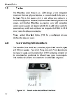
Page 56: ...k as a control interface for the laser Orientation of the pinhead has to be taken into account when connecting a control interface to the laser To find out more about laser pinout see Power and Signal...

Page 57: ...r perfection and diversity our engineers and researchers work hard everyday to make improvements of our products especial in new products newly created equipment Henceforth accessories in MatchBox use...

Page 58: ...Integrated Optics 56...

Page 59: ...y for higher power direct diode or DPSS lasers We highly recommend to use the same power supply as we offer on our website Otherwise we can not ensure that the laser would work the same as it was test...

Page 60: ...table for heatsinking DPSS lasers User s should always use thermal paste when mounting the laser Body temperature of the laser should not exceed about 40 C and the TEC load should not exceed 80 with r...

Page 61: ...A We recommend to use FC APC for SLM lasers this is to avoid back reflections from a polished fiber tip to the laser cavity In all other cases both FC PC or FC APC connectors can be used depending on...

Page 62: ...be that heat dissipation is not sufficient if so TEC load will be about 100 You should also check how much Amperes does the laser consume it should be no more than 1 5 A for diode lasers and typicall...

Page 63: ...page 46 Q Is AM H8 cooler suitable with DPSS lasers A Unfortunately DPSS lasers require a better cooling system The most suitable coolers in this case would be TEC based heatsinks AM H9 AM H10 or AM...

Page 64: ...ncy of the photodiode then wavelength change of hundreds of pico meters can change the response of the photodiode Please adjust the DAC value to restore the power level If the power of the laser was c...

Page 65: ...Control APC Automatic power control BoB Break out Box bps Bytes Per Second CCD Charge coupled device CDRH Centre for Devices and Radiological Health cm Centimetre CW Continuous Wave DAC Digital to Ana...

Page 66: ...rad Milli radian 10 3 radians mW Milliwatt 10 3 Watts nm Nanometre 10 9 meter N m Newton metre NTC Negative Temperature Coefficient OEM Original Equipment Manufacturer PCB Printed Circuit Board PM Pol...

Page 67: ...r serial communication transmission of data Rx Receive SLM Single Longitudinal Mode TEC Thermo Electric Cooler TTL Transistor Transistor Logic Tx Transmit UART Universal Asynchronous Receiver Transmit...

Page 68: ...Integrated Optics 66...

Page 69: ...whichever occurs first Operational time calculation is based on an internal EPROM coun ter The Buyer is responsible for providing the appropriate utilities and an operating environment as outlined in...

Page 70: ...buyer Buyer supplied interfacing Operation outside the environmental specifications of the product Unauthorized modification or misuse Improper site preparation and maintenance or Opening the laser ho...

Page 71: ...MatchBox series User Manual 69...

Page 72: ...Integrated Optics 70...

Reviews: