background image

8

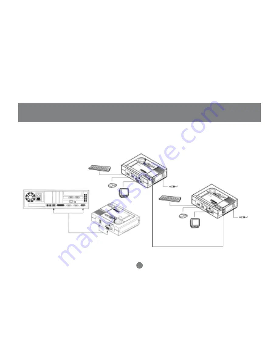
Installation

Setting up the USB KVM Console Extender System is simply a matter of plugging
in the cables:

GCE700 Local Unit Front View

GCE700 Local Unit Rear View

GCE700 Remote Unit

Summary of Contents for GCE700

Page 1: ...USB KVM Console Extender User Manual GCE700 ...

Page 2: ......

Page 3: ...se of the Auto Signal Compensation ASC technology which senses the distance and adjusts the signal levels accordingly so there is no need to do any dip switch setting We hope that you will enjoy using your USB KVM Console Extender and find it to be a useful solution 2003 IOGEAR All Rights Reserved PKG M0070 IOGEAR the IOGEAR logo MiniView MiniView II MiniView SE MasterView and VSE are trademarks o...

Page 4: ...eatures System Requirements Introduction Installation Operation Troubleshooting Twisted Pair Wiring Diagram Twisted Pair Pin Assignment Specification Technical Support Radio TV Interference Statement Limited Warranty 02 03 04 05 08 11 13 14 15 16 17 18 19 ...

Page 5: ...ge contains 1 USB KVM Console Extender Local Unit 1 USB KVM Console Extender Remote Unit 1 Custom KVM Cable 2 Power Adapters 1 User Manual 1 Warranty Registration Card If any items are missing or damaged please contact your dealer ...

Page 6: ...tion control your system from both local and remote USB keyboards USB mice and monitors USB over current detection and prevention Easy to operate push button selection between local and remote console High video resolution up to 1280 x 1024 Supports VGA SVGA and Multisync monitors Local monitor supports DDC DDC2 DDC2B Hot pluggable Plug n Play no need for any software driver installation ...

Page 7: ... mouse Computers VGA SVGA or Multisync card Available USB port Cables Category 5e rated UTP Unshielded Twisted Pairs cable with solid conductors is the minimum requirement to connect the GCE700 local unit to the GCE700 remote unit Cable of a lesser standard will result in degrading of the video signal For best performance we strongly recommend Category 5e or Category 6 cables ...

Page 8: ...the system s 2 LEDs The Local Unit has two LEDs to indicate the operating status of the Local and Remote units 3 USB Keyboard and Mouse Ports The local USB Keyboard and local USB mouse plug into these ports 4 Monitor Port The local monitor plugs into this port 5 Remote I O The Category 5e cable that connects to the Remote Unit plugs into this port 6 Power Jack The cable from the AC Power Adapter p...

Page 9: ...ear View 1 USB Port Plug the USB Type B connector of the USB KVM Cable supplied with this package in here 2 Monitor Port The HDB 15 VGA Connector of the USB KVM Custom Cable supplied with this package plugs in here Introduction ...

Page 10: ...cal and Remote units 2 USB Keyboard and Mouse Port The remote USB keyboard and USB mouse plug into these ports 3 Monitor Port The remote monitor plugs into this port 4 Remote I O The Category 5e cable that connects back to the Local Unit plugs into this port 5 Power Jack The cable from the AC Power Adapter plugs into this jack Introduction ...

Page 11: ...8 Installation Setting up the USB KVM Console Extender System is simply a matter of plugging in the cables GCE700 Local Unit FrontView GCE700 Local Unit RearView GCE700 Remote Unit ...

Page 12: ...th an appropriate icon to indicate what it is 4 Plug the connectors on the other end of the cable into the appropriate ports on the computer system or Console section of the USB KVM switch Each connector is marked with an appropriate icon to indicate what it is 5 Plug either end of the Category 5e cable into the Remote I O port of the Local Unit 6 Plug one of the power adapters supplied with this ...

Page 13: ... console devices USB mouse USB keyboard monitor into their ports on the Console side of the Remote Unit 9 Plug the second power adapter supplied with this package into an AC source plug the adapter s power cable into the Power Jack of the Remote Unit ...

Page 14: ...tch from either local or remote console You can select either local or auto by pushing the SELECT button The auto mode allows either console to take over and allow the other console to view The Local and Remote Units each have two LEDs to indicate their operating status as shown in the tables below ...

Page 15: ...N O F F O y d a e R t o N F F O F F O e v i t c A e l o s n o C r e h t i e N N O N O e d o M g n i t a r e p O s D E L s u t a t S e n i l n O e v i t c A e l o s n o C l a c o L F F O N O e v i t c A e l o s n o C e t o m e R H S A L F N O t c e n n o c s i D r o r r E F F O H S A L F y d a e R t o N F F O F F O e v i t c A e l o s n o C r e h t i e N N O N O Operation Local Unit Remote Unit ...

Page 16: ...t a h t e r u s e k a M e h t g n i h c a e r t o N d e i f i c e p s e c n a t s i d d i l o s h t i w e l b a c 6 y r o g e t a C r o e 5 y r o g e t a C e s u u o y t a h t e r u s e k a M e c n a t s i d e h t t c e f f a l l i w s e l b a c h c t a p d e d n a r t s g n i s U s r o t c u d n o c Troubleshooting Troubleshooting ...

Page 17: ...T568B AT T 568A 14 Twisted PairWiring Diagram Twisted Pair Wiring Diagram ...

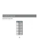
Page 18: ...15 Twisted Pair Pin Assignments Twisted Pair Pin Assignments n i P t n e m n g i s s A 1 B T U O V 2 B T U O V 3 G T U O V 4 R T U O V 5 R T U O V 6 G T U O V 7 O D 8 O D ...

Page 19: ...b y e K B e p y T B S U A N o e d i V e l a M B D H n i p 5 1 x 1 A N s D E L l a c o L 1 e t o m e R 1 s u t a t S 1 e n i L n O 1 s y e K n o i t c n u F n o t t u B t c e l e S o t u A l a c o L A N h t g n e L e l b a C m u m i x a m t f 0 0 5 m 0 5 1 n o i t u l o s e R o e d i V B 2 C D D 2 C D D C D D 4 2 0 1 x 0 8 2 1 n o i t p m u s n o C r e w o P W 8 6 V 9 C A W 4 7 V 9 C A g n i s u o ...

Page 20: ... hours a day Please be ready to give a brief description of the problem and what you were doing when the problem occurred before calling Service Support The Service Support representative will be able to serve you much quicker if you are prepared to answer the following questions listed below 1 What version of OS are you using 2 What type of computer are you using 3 Can the problem be reproduced I...

Page 21: ...equipment has been tested and found to comply with the limits for a Class B computing device pursuant to Subpart J of Part 15 of FCC Rules which are designed to provide reasonable protection against such interference when operated in a commercial environment Operation of this equipment in a residential area is likely to cause interference in which case the user at his own expense will be required ...

Page 22: ... warranty or representation expressed implied or statutory with respect to the contents or use of this documentation and especially disclaims its quality performance merchantability or fitness for any particular purpose The direct vendor also reserves the right to revise or update the device or documentation without obligation to notify any individual or entity of such revisions or updates For fur...

Page 23: ......

Page 24: ...23 Hubble Irvine CA 92618 P 949 453 8782 F 949 453 8785 www iogear com Contact info ...

Reviews: