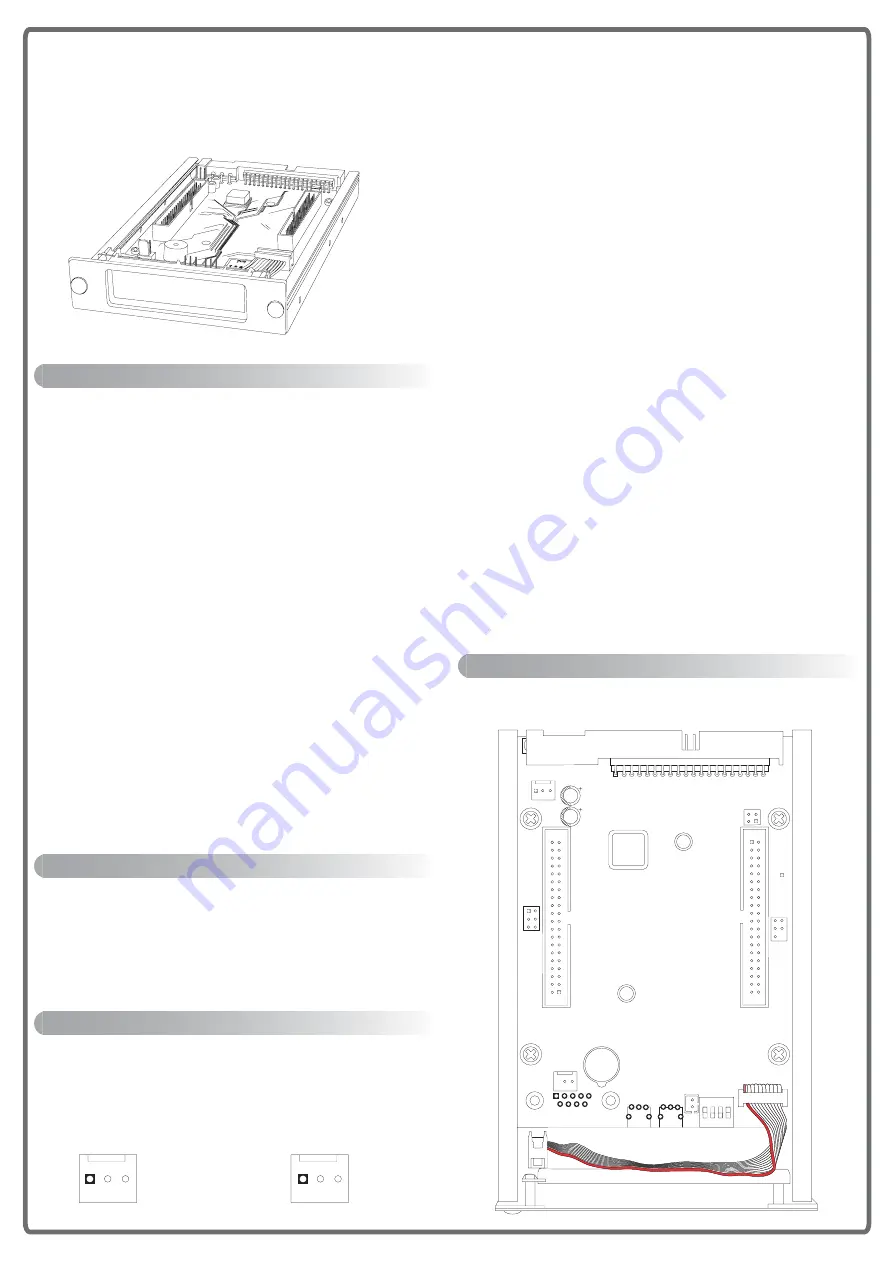
Introduction:
Connectors:
RAID Management:
JP1:
Master / Slave Seletion
Pin1-2: Set ATA2ATAR01 to Cable Select
Pin3-4: Set ATA2ATAR01 to Master Mode
OPEN: Set ATA2ATAR01 to Slave Mode
JP2 & JP3:
X-ATA Port Setting
For RAID 1 mode
- With KTCIDEMR:
JP2 (1-2) & JP3 (1-2)
- With HDD direct attach or standard IDE mobile rack
JP2 (2-3) & JP3 (1-2)
For RAID 0\ NRAID\ X_M/Y_S (JBOD)
- JP2 (2-3) & JP3 (2-3)
JP4 & JP5:
Y-ATA Port Setting
For RAID 1 mode
- With KTCIDEMR:
JP4 (1-2) & JP5 (1-2)
- With HDD direct attach or standard IDE mobile rack
JP4 (2-3) & JP5 (1-2)
For RAID 0\ NRAID\ X_M/Y_S (JBOD)
- JP4 (2-3) & JP5 (2-3)
BT1:
Buzzer Controle Button
ON: Enable OFF: Disable
SW1-1:
Buzzer Control
ON: Enable OFF: Disable
SW1-2:
Firmware Upgrade
ON: Enable OFF: Disable
SW1:
RAID Mode selection
SW1-3 SW1-4
RAID 0
OFF
OFF
RAID 1
OFF
ON
NRAID
ON
OFF
X_M/Y_S(JBOD) ON
ON
Physical Dimensions:
10.16cm (W) x 2.54cm (H) x 12.95cm(D)
ATA2ATAR01 is a ATA -RAID- ATA Subsystem.
ATA2ATAR01 is designed in 3.5" FDD (Floppy Disk Drive)
form factor.
*Easy to install and operate
*Support RAID 0, 1 and SPAN
*Plug-and-play, require no device driver
*OS Independence, require no device driver
*Big Drive Supported ( > 137GB )
*Hot-Swap Supported (optional)
*Auto-Rebuild Support (optional)
*Hi-Speed Auto-Rebuilding ( around 70GB/hour )
*Manual-Rebuild Supported
*Support up to UDMA 133
*High Hard Disk Compatibility and Performance
*With LCD Display Panel:
- To simplify the RAID status monitoring.
- Uses hardware monitor to monitor HDD status, Temperature
and Fan activity.
- Displays warning message on LCD screen when respective
disk encounters problems.
*Provides a fan fail detector and temperature detector and buzzer
driver circuit.
*Provides alarm disable Button/Switch.
*Provides One RS-232 Port for RAID Management
*EagleEye RAID Manager :
- EagleEye RAID Manager is a software utility to monitor RAID operating
status and display RAID system information on the screen
- For Fireware update
J1:
Host ATA Port
J2:
X -ATA Port
J3:
Y -ATA Port
J4:
LCD Connector (Pin 1 is Red color )
J5:
Fan Connector
CN2A:
RS-232 Port
GND 12V CLK
TX RX
GND
2
1
40
39
39
40
1
2
SW1
J4
J3
J2
JP3
JP2
J5
J1
BT1
CN2A
JP1
1 2 3 4
O N
3
1
4
2
1
9
2
10
SW1-2:
Firmware
Upgrade
On:
Enable
OFF:
Disable
SW1-1:
Buzzer
Control
On:
Enable
OFF:
Disable
Master
/
Slave
Seletion
Pin1-2:
Cable
Select
Pin3-4:
Master
Mode
OPEN:
Slave
Mode
FA
N
RS-232
JP2
&
JP3:
RAID
mode
selection
1-2
RAID
1
2-3
RAID
0
\
NRAID
\
X_M/Y_S
JP4
&
JP5:
RAID
mode
selection
1-2
RAID
1
2-3
RAID
0
\
NRAID
\
X_M/Y_S
RAID
Mode
selection
SW1-3
SW1-4
RAID
0
OFF
OFF
RAID
1
OFF
ON
NRAID
ON
OFF
X_M/Y_S
ON
ON
Y-
A
T
A
X-
A
T
A
JP4
JP5
4).IDE -RAID- IDE Subsystem
ATA2ATAR01
Overview


