background image

14140 NE 200th St. 

Woodinville, WA.  98072

(425) 398-8282

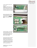
Connect all wires to new main 

logic board.

Caution:

 It is VERY important to 

make a proper connection. If a row 

of pins is missed or the cable is not 

plugged in correctly, you can do per-

manent damage to the main board.

Make sure the ribbon cables lay 

nicely and tighten the tyrap hold-

ing the ribbon cable but not so 

tight as to damage the cable.

Install the bottom cover and then 

rotate machine back to normal 

operating position. Make sure to 

install screws that hold the ma-

chine on the stand legs.

Follow the procedure for  ‘Motion 

Adjustment’ on Page 52 in the 

Ioline FJ Printer and StudioJet Ser-

vice Manual. The Service manual 

is available from the Ioline FlexJet 

website. Contact Ioline Tech Sup-

port for login information.

If problems arise, contact Ioline 

Tech Support.

Summary of Contents for FJ8

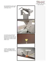
Page 1: ...or cable from the bottom right side of the machine Remove the Rear Stand Screws on the rear of the machine These hold the printer on the stand do not remove the front screws Make sure the stop screws are installed on the take up plate on both sides of the machine Take Up Motor Cable Rear Screw Left Side Rear Screw Right Side Front Screw DO NOT REMOVE Front Stop Screw DO NOT REMOVE P N 108854 R0 ...

Page 2: ... on the stop screw Front Stop Screw Locate the screws on the bot tom cover and remove only the bottom cover closest to the keypad of the machine Stand ing behind the machine it will be the left cover Carefully unplug the bottom cover sensor cable from the bottom cover before removing completely Sensor Plug Sensor ...

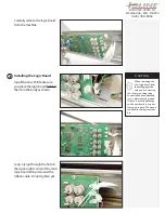
Page 3: ... the main logic board When removing the new logic board from the packaging make sure you are wearing the static grounding strap correctly and have attached it to a metal chassis ground If there is a static discharge to the new board it may not function properly The strap is included in the replacement kit Caution Tools Required n Phillips head screwdriver n Tyrap 1 P N 108854 R0 2 Unplug all conne...

Page 4: ...e in the upper right corner of the main logic board Wrap it around the ribbon cable Do not tighten yet When removing the new logic board from the packaging make sure you are wearing the static grounding strap correctly and have attached it to a metal chassis ground If there is a static discharge to the new board it may not function properly The strap is included in the replacement kit Caution 3 In...

Page 5: ...e tyrap hold ing the ribbon cable but not so tight as to damage the cable Install the bottom cover and then rotate machine back to normal operating position Make sure to install screws that hold the ma chine on the stand legs Follow the procedure for Motion Adjustment on Page 52 in the Ioline FJ Printer and StudioJet Ser vice Manual The Service manual is available from the Ioline FlexJet website C...

Reviews: