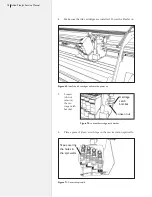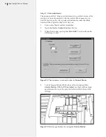
77
Chapter 4: Repair Procedures
Service station procedures
Y Fine adjustment for the Service Station
This procedure must always be done after replacing or upgrading
the carriage assembly.
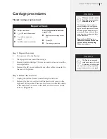
Tools Required
n
Scotch tape
n
Phillips screwdriver
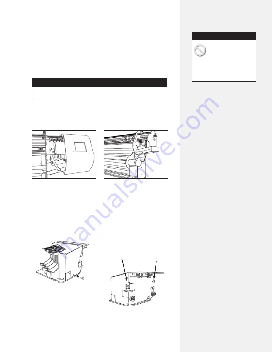
Step 1: Service station centering
1.
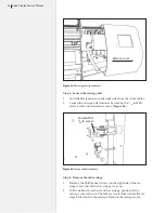
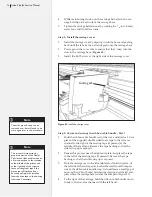
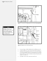
Remove power and communications cables and the right side
cover. (
Figure 66
.)
2.
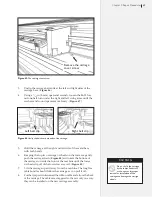
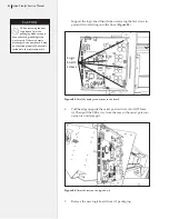
Remove the four Phillips screws that hold the keypad on. Let
the keypad hang. Make sure both ends are still plugged in.
(
Figure 67
.)
3.
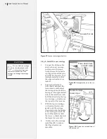
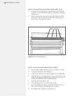
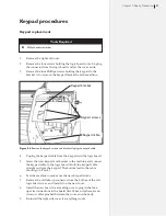
Remove the carriage cover. (One screw on the right side, un-
clip the back right and left sides.
Figure 68
.)
Figure 66.
Remove the right end cover.
Figure 67.
Remove the screws and let the
keypad hang.
Figure 68.
Remove the carriage cover.
Screw
Pull out on the tabs
to remove the cover
The discharge of static
electricity may damage the
keypad and components.
Use the included ground strap
during all procedures. Keep plastic
objects away from the keypad and
logic board assemblies.
Caution
Summary of Contents for FlexJet
Page 1: ...Service Manual Ioline FlexJet ...
Page 3: ...Service Manual Ioline FlexJet ...
Page 4: ......
Page 8: ......
Page 12: ......
Page 60: ...60 Ioline FlexJet Service Manual This page intentionally left blank ...
Page 90: ...90 Ioline FlexJet Service Manual This page intentionally left blank ...
Page 96: ...96 Ioline FlexJet Service Manual This page intentionally left blank ...

