Images & Illustrations
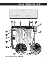
Figure 1
The Ioline SmarTrac I/S cutter front view ............................................................. x
Figure 2
The Ioline SmarTrac Contour (SC) cutter front view ....................................... xi
Figure 3
The Ioline SmarTrac SC-72 cutter front view .................................................... xii
Figure 4
The Ioline SmarTrac Contour SC-72 cutter rear view ................................... xiv
Figure 5
Power and communications ports .............................................................................xiv
Figure 6
USB Connection ....................................................................................................... 17
Figure 7
Ignore the Windows
®
XP Warning ........................................................................ 17
Figure 8
Click Next when the
New Hardware Wizard
window appears .............. 17
Figure 9
Locate the USB driver folder ................................................................................. 18
Figure 10
Find the COM port number under the
Device Manager
window ............ 18
Figure 11
Setup the software for USB .................................................................................... 19
Figure 12
Enter the port settings under the
Device Manager
window ...................... 19
Figure 13
The Ioline
Control Center Installation
window. ........................................ 20
Figure 14
The SmarTrac keypad ............................................................................................... 21
Figure 15
Origin point ................................................................................................................ 22
Figure 16
The
Control Center Setup Screen
............................................................... 23
Figure 17
The
Control Center Main Menu
.................................................................... 24
Figure 18
Adjusting pinchwheel presure ................................................................................ 31
Figure 19
Locking the idler pinchwheels off the platen ...................................................... 31
Figure 20
Installing the blade and blade foot in the holder ............................................... 32
Figure 21
Installing the blade holder in the carriage jaw .................................................... 32
Figure 22
When properly exposed, the blade lightly scores the backing ....................... 33
Figure 23
Suggested settings for different materials ............................................................ 35
Figure 24
Plotting pen guidelines ............................................................................................. 36
Figure 25
The Tangential Panel ................................................................................................. 40
Figure 26
Rectangular registration marks .............................................................................. 41
Figure 27
Recommended registration mark dimensions .................................................... 41
Figure 28
Registration marks margin ...................................................................................... 42
Figure 29
Registration mark locations on plot ..................................................................... 42
Figure 30
Replacing the blade ................................................................................................... 49
Figure 31
Cleaning the drive shaft ........................................................................................... 50
Figure 32
The
Calibration Box
and measurements ........................................................ 51
Figure 33
Print and measure a 1-cm black square on a white background ................... 52
Figure 34
Registration tool in jaw ............................................................................................ 52
Figure 35
Align tool with the corner of the box ................................................................. 52
Figure 36.
The
Control Center
Calibration
window ..................................................... 53
Figure 37.
The
Small Sensor
Calibration window .........................................................................54


