1 3
1 3
1 3
1 3
1 3
Models 20 to 30 are equipped with a differential pressostat as standard equipment. The pressostat detects water
pressures losses across the evaporators and shuts down the unit in the event of an anomaly occurring.
On models 40 to 60, a water flow controller is fitted instead of the differential pressostat.
In addition:
➢
Install stop cocks on the evaporator water inlet and outlet pipes.
➢
Install an evaporator by-pass with a stop cock.
➢
Install air bleed valves at the highest points on the pipe links.
➢
Install suitable system drainage points (with take-offs, taps, etc.) on the lowest points on the pipe links.
➢
Insulate all pipe work to prevent heat losses.
Prior to filling the system, ensure that it contains no foreign bodies (sand, stones, rust or brazing flakes,
swarf) or any other material that might damage the evaporators.
The water used to fill the circuit should be treated, as required, to ensure a correct pH value.
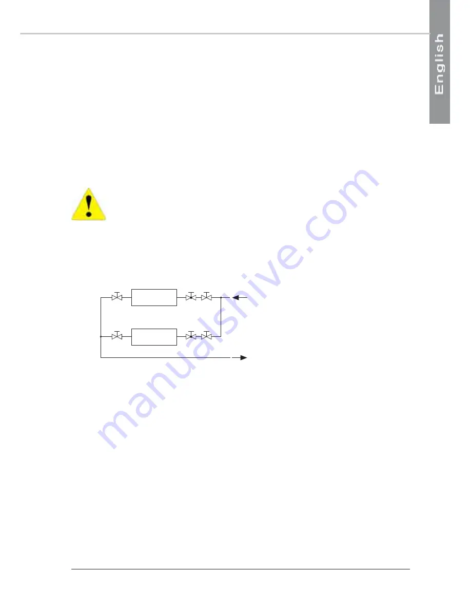
When two or three units are connected in parallel, it is recommended that the return circuit connections are reversed
(see below) in order to reduce the pressure loss in each unit’s circuit.
UNITA' 1
UNITA' 2
N°1
N° 2
S
VG
S
S
VG
S
S : Taps/stop cocks
VG : Balancing valves
The standard evaporators fitted to AQC units are designed for cooling solutions of water and ethylene glycol, with an
anti-corrosion additive, for protection down to temperatures of -8 °C (R 407C).
Refer to the Appendix for the quantity of ethylene glycol to be added.
The quantities are defined as a percentage in relation to the theoretical weight of water contained in the circuit.
The inlet and outlet water pipe links must be connected correctly, as indicated on the labels situated close to the pipe
unions.
Connect the external water supply pipes to the unit’s water inlet and outlet unions.
SEE APPENDIX
SEE APPENDIX
SEE APPENDIX
SEE APPENDIX
SEE APPENDIX
HYDRAULIC CIRCUIT DIAGRAM
HYDRAULIC CIRCUIT DIAGRAM
HYDRAULIC CIRCUIT DIAGRAM
HYDRAULIC CIRCUIT DIAGRAM
HYDRAULIC CIRCUIT DIAGRAM


