2 1
2 1
2 1
2 1
2 1
HYDRAULIC CIRCUIT
HYDRAULIC CIRCUIT
HYDRAULIC CIRCUIT
HYDRAULIC CIRCUIT
HYDRAULIC CIRCUIT
1. Start the liquid pump and check that the water flow is within the prescribed rates.
2. Programme the desired inlet fluid temperature on the control panel.
3. After about 15 minute’s operation, check that there are no air bubbles in the liquid pipe by looking
through the liquid inspection porthole.
The presence of air bubbles means that the unit has lost some of its refrigerant charge
The presence of air bubbles means that the unit has lost some of its refrigerant charge
The presence of air bubbles means that the unit has lost some of its refrigerant charge
The presence of air bubbles means that the unit has lost some of its refrigerant charge
The presence of air bubbles means that the unit has lost some of its refrigerant charge
via one or several leakage points that should be eliminated.
via one or several leakage points that should be eliminated.
via one or several leakage points that should be eliminated.
via one or several leakage points that should be eliminated.
via one or several leakage points that should be eliminated.
➢
Plug the leaks.
➢
Check the oil level.
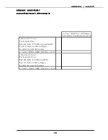
Operating conditions:
➢
Pipe link lengths: 7.5m
➢
Nominal unit airflow
➢
Heating mode
Temperature
♦
Water: 40 / 45°C
♦
Air: 7°C (DB) / 6°C (WB)
➢
Cooling conditioning mode
Temperature
♦
Water: 12 / 17°C
♦
Air: 35°C (DB)
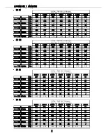
The compressor outlet pressure is a parameter providing a check that the unit is charged with the correct amount of
refrigerant.
A low outlet temperature corresponds to an excessive charge.
A high outlet temperature corresponds to an insufficient charge.
INDICATIVE VALUES OF NORMAL OPERATION OF THE EQUIPMENTS.
COOLING HEATING COOLING HEATING COOLING HEATING COOLING HEATING COOLING HEATING COOLING HEATING
Outlet pressure
bar
Inlet pressure
bar
Outlet temperature
°C
Inlet temperature
°C
60
30
35
40
50
25
Blown air T° / Interior air
°Cdb / °Cwb
°C
MODELS


