background image

2 3

2 3

2 3

2 3

2 3

The user is responsible for ensuring that the unit is in proper working order and that technical installation
as well as the regular maintenance operations are performed by properly trained technicians and in
accordance with the instructions contained in this manual.

MAINTENANCE

MAINTENANCE

MAINTENANCE

MAINTENANCE

MAINTENANCE

REGULAR MAINTENANCE

REGULAR MAINTENANCE

REGULAR MAINTENANCE

REGULAR MAINTENANCE

REGULAR MAINTENANCE

These units have been designed for minimum maintenance through the use of permanently lubricated components.
However, there are operational maintenance requirements that require regular attention to ensure optimum performance.

Maintenance must be performed by appropriately experienced personnel.

WARNING : 

WARNING : 

WARNING : 

WARNING : 

WARNING : Isolate unit from power supply before working on unit.

REMO

REMO

REMO

REMO

REMOV

V

V

V

VAL OF P

AL OF P

AL OF P

AL OF P

AL OF PANELS

ANELS

ANELS

ANELS

ANELS

All access panels are removable by unscrewing the self tapping retaining screws.

F

FF

FFAN DRIVE SYSTEM

AN DRIVE SYSTEM

AN DRIVE SYSTEM

AN DRIVE SYSTEM

AN DRIVE SYSTEM

Fan shaft and motor bearings are of permanently lubricated, sealed type and require no regular maintenance other than
a check on their general condition. The fan belt tension should be checked regularly and belt surfaces inspected for
cracks or excessive wear. The belt should be tensioned to give a 20 mrn deflection under medium pressure with the
thumb on one of the straight runs.

COILS

COILS

COILS

COILS

COILS

The coil surface will become laden with dust and maybe blocked by leaves or papers over a period of time. Coils should
be inspected periodically and cleaned down by hosing or steam cleaning as required.

ELECTRICAL

ELECTRICAL

ELECTRICAL

ELECTRICAL

ELECTRICAL

The contact surfaces of relays and contactors should be inspected regularly by an electrician and replaced as judged
necessary. On these occasions the control box should be blown out with compressed air to remove any accumulation of
dust or other contaminants.

REFRIGERA

REFRIGERA

REFRIGERA

REFRIGERA

REFRIGERATION

TION

TION

TION

TION

The refrigeration system is hermetically sealed and should require no regular maintenance. However, it is recommended
that the system must be leak tested and the general operating and control systems be checked on a regular basis. The
operating pressures should be checked particularly as they are an excellent guide of the system in need of maintenance.

Summary of Contents for AQCH 25

Page 1: ...Manual de instalacion y de mantenimiento IOM AQC 01 O 1GBF Part number Code code Codice Código 3990256 Supersedes Annule et remplace annulliert und ersezt Annulla e sostituisce anula y sustituye None Néant Nichht Nulla Ninguno AQCL AQCH AQU LOGIC CENTRIFUGAL COOLING AND HEATPUMP MODEL 25 30 35 40 50 60 CHILLED WATER UNIT UNITE DE PRODUCTION D EAU GLACEE ...

Page 2: ...NST INST INSTALLA ALLA ALLA ALLA ALLATION TION TION TION TION 1 1 1 1 1 1 1 1 1 1 CLEARANCE 11 LOCATING THE UNIT 11 DE ICING WATER DRAINAGE AQCH MODELS ONLY 12 ANTI VIBRATION SPRING MOUNTED PADS INSTALLATION 12 HYDRAULIC CONNECTIONS HYDRAULIC CONNECTIONS HYDRAULIC CONNECTIONS HYDRAULIC CONNECTIONS HYDRAULIC CONNECTIONS 1 2 1 2 1 2 1 2 1 2 HYDRAULIC CIRCUIT DIAGRAM 13 WIRING DIAGRAM AND LEGEND WIRI...

Page 3: ...uired electric current of operation taking into account specific conditions of the location and the current required for any other appliance connected with the same circuit The unit must be EARTHED to avoid any risks caused by insulation defects It is forbidden to start any work on the electrical components if water or high humidity is present on the installation site WARNING WARNING WARNING WARNI...

Page 4: ...orrect installation commissioning or use and or insufficient maintenance It also declines all liability for personal injuries and materiel damage resulting from non compliance with the procedures and instructions contained in the present manual WARRANTY WARRANTY WARRANTY WARRANTY WARRANTY The appliances are delivered fully assembled factory tested and ready to operate Any modification to the units...

Page 5: ...to contact with wet fabrics the liquid refrigerant will cause them to freeze and adhere to the skin Carefully remove the contaminated clothing since it might adhere to the skin and cause freeze burns Apply to a doctor if the affected skin areas should be reddened or irritated Vapours have no effect Liquid splashes or sprays may cause freeze burns In these cases rinse your eyes with running water o...

Page 6: ...istered letter to the shipper within 48 hours clearly stating the damage caused Forward a copy of this letter to the manufacturer or their representative caused Forward a copy of this letter to the manufacturer or their representative caused Forward a copy of this letter to the manufacturer or their representative caused Forward a copy of this letter to the manufacturer or their representative cau...

Page 7: ...de and 30 bar refrigerant side The evaporator is protected against freezing by an electric resistance a differential pressure pressostat for models 20 to 30 and a flow controller for models 40 to 80 CONDENSER BA CONDENSER BA CONDENSER BA CONDENSER BA CONDENSER BATTERIES TTERIES TTERIES TTERIES TTERIES The condenser batteries are made of weld free copper pipes that are arranged in staggered rows an...

Page 8: ...ling standards They depend on the system installed and the cables used AERA AERA AERA AERA AERAULIC TECHNICAL SPECIFICA ULIC TECHNICAL SPECIFICA ULIC TECHNICAL SPECIFICA ULIC TECHNICAL SPECIFICA ULIC TECHNICAL SPECIFICATIONS TIONS TIONS TIONS TIONS Packaged model 25 30 35 40 50 60 Refrigerant charge 6 500 g 7 050 g 7600 8500 g 13760 g 16000 g 25 30 35 40 50 60 Power supply 3N 400 V 50 Hz Cooling F...

Page 9: ...T WEIGHT WEIGHT A B C 25 1505 1750 890 30 1505 1750 890 35 1505 1750 890 40 1773 2206 890 50 1773 2206 890 60 1773 2206 890 AQCL AQCH 25 387 kg 395 kg 30 405 kg 420 kg 35 415 kg 435 kg 40 575 kg 580 kg 50 630 kg 650 kg 60 660 kg 670 kg NET WEIGHT COOLING ONLY AND HEATPUMP Use spreaders HANDLING HANDLING HANDLING HANDLING HANDLING ...

Page 10: ...150 1350 250 1115 350 1600 950 35 150 1350 250 1115 350 1600 950 40 285 1400 530 1275 450 2010 1085 50 285 1400 530 1275 450 2010 1085 60 285 1400 530 1275 450 2010 1085 VERTICAL BLOWING VERTICAL BLOWING VERTICAL BLOWING VERTICAL BLOWING VERTICAL BLOWING A B C D 25 109 348 252 1348 30 109 348 252 1348 35 109 348 252 1348 40 215 445 595 1490 50 215 445 595 1490 60 215 445 595 1490 A B C D E 25 185 ...

Page 11: ...ons depend on the facory configuration The unit base shall be arranged as indicated in the manual There could be a risk of personal injury or damage to property in the event of the unit being incorrectly supported The unit must be installed on a firm level foundation of adequate strength to support its full operating weight 1 It must be high enough to permit good drainage of defrost water and allo...

Page 12: ...through the base hole Check that the unit is positioned correctly on the washers E Turn the nut D with a 13 mm spanner to adjust the height as required Lock the position with the spring washer F and the nut C After installation check the correct operation of the pads HYDRAULIC CONNECTIONS HYDRAULIC CONNECTIONS HYDRAULIC CONNECTIONS HYDRAULIC CONNECTIONS HYDRAULIC CONNECTIONS The external water sys...

Page 13: ...required to ensure a correct pH value When two or three units are connected in parallel it is recommended that the return circuit connections are reversed see below in order to reduce the pressure loss in each unit s circuit UNITA 1 UNITA 2 N 1 N 2 S VG S S VG S S Taps stop cocks VG Balancing valves The standard evaporators fitted to AQC units are designed for cooling solutions of water and ethyle...

Page 14: ...ring of this unit shall comply with local electrical installation standards Thee phase 400 V Neutral Ground On terminals P E N L1 L2 L3 on Main Terminal Block X1 Three phase 400V Ground Models 40 to 80 only Transformer option obligatory On terminals P E L1 L2 L3 and Ground on Main Terminal Block X1 25 32 A 25 A 80 A 30 32 A 27 A 82 A 35 40 A 31 A 122 A 40 50 A 44 A 140 A 50 50 A 46 8 A 186 A 60 63...

Page 15: ...ls ACS Three phase frequency converter with RFI filter SEE INSTALLATION MANUAL COOLING COOLING COOLING COOLING COOLING M1 M2 Refrigerating compressor KS1 KS2 Internal safeties of compressors M1 M2 mod 40 50 60 K1 K2 Compressor power contactor M1 M2 FT1 FT2 Thermo magnetic compressor circuit breaker M1 M2 mod 25 30 HP1 High pressure pressostats automatic reset FPC Condenser pressure transducer FPE ...

Page 16: ...SSE A ORS CLASSE A ORS CLASSE A ORS CLASSE AC3 C3 C3 C3 C3 25 30 35 40 50 60 range 9 14 A 9 14 A 13 18 A 13 18 A 20 25 A 20 25 A Adjustment 10 A 11 5 A 13 A 16 A 21 A 23 A range 9 14 A 9 14 A 9 14 A 13 18 A 13 18 A 13 18 A Adjustment 10 A 11 5 A 11 5 A 13 A 13 A 16 A range 1 6 2 5 A 1 6 2 5 A 1 6 2 5 A 1 6 2 5 1 6 2 5 2 5 4 A Adjustment 1 7 A 1 7 A 1 7 A 2 1 A 2 1 A 3 1 A range 6 10 A 6 10 A 6 10 ...

Page 17: ...n accordance with local electrical standards and the wiring diagram corresponding to the unit model Any modification performed without our prior authorisation may result in the unit s warranty being declared null and void The power supply cable section must be sufficient to provide the appropriate voltage to the unit s power supply terminals both at start up and under full load operating condition...

Page 18: ...n power supply of the unit in accordance with the circuit diagram for the raitings refer to the electrical specifications Use a pozidrive M3 5 screwdriver Form Z to make the connections Press to unclip and withdraw the local switch unit on the terminal board Max tightening torque models 25 30 35 2 1Nm models 40 50 60 4Nm 3N 400V 3N 400V 3N 400V 3N 400V 3N 400V Models 25 30 35 Models 40 50 60 ...

Page 19: ...e concentration level is correct 3 Check the direction of rotation of the pump and leave the fluid to circulate for at least 12 hours for each pump Then clean the pump inlet water filter 4 Adjust the water flow in order to comply with the specifications 5 Check that the water quality complies with the indicated standards 6 Check that the oil heating resistances have been energised for at least 12 ...

Page 20: ...ONTROL 1 Operate system switches and control thermostat 2 Check unit is wired for correct control of unit fan cooling and heating functions 3 Verify all sensor input using the ILTC controller display FAN DRIVE FAN DRIVE FAN DRIVE FAN DRIVE FAN DRIVE 1 Check that the Sheaves on both the fan shaft and the motor are correctly fitted to the bush and rotate without wobble 2 Check the alignment of the p...

Page 21: ...several leakage points that should be eliminated via one or several leakage points that should be eliminated via one or several leakage points that should be eliminated via one or several leakage points that should be eliminated via one or several leakage points that should be eliminated Plug the leaks Check the oil level Operating conditions Pipe link lengths 7 5m Nominal unit airflow Heating mod...

Page 22: ...ales Department To return the material contact your nearest sales office and ask for a return voucher This return voucher shall be sent out with the returned material and shall contain all necessary information concerning the problem encountered The return of the part does not constitute an order for replacement Therefore a purchase order must be entered through your nearest distributor or regiona...

Page 23: ...ings are of permanently lubricated sealed type and require no regular maintenance other than a check on their general condition The fan belt tension should be checked regularly and belt surfaces inspected for cracks or excessive wear The belt should be tensioned to give a 20 mrn deflection under medium pressure with the thumb on one of the straight runs COILS COILS COILS COILS COILS The coil surfa...

Page 24: ...leys and the drive belt 4 Check the drive belt tension 5 Check for signs of wear on the fan bearings PROTECTION DEVICES Check the proper operation of the high pressure regulation system ELECTRICAL EQUIPMENT 1 Check nominal current draw and the condition of the fuses 2 Check the tightness of the screw terminals 3 Perform a visual check of the condition of the contacts 4 Check the general tightness ...

Page 25: ...its thermal protection cuts in Check the operation of the control and safety devices Identify and eliminate the cause of the activation Incorrect wiring Check the wiring of the control and safety devices Mains voltage too low Check the power line Eliminate any possible problems associated with the system If the problem is due to the network inform the Electricity Company Compressor motor short cir...

Page 26: ...ntrol panel Incorrect temperature differential between evaporator inlet and outlet Check the water flow and the quantity of liquid in the water circuit Electronic control system malfunction Contact an approved Service Centre Air in the circuit Bleed the air via the safety valve Deposits or impurities in the evaporator Wash out the evaporator by back flushing Water circulation fault Check the pump ...

Page 27: ...NNEXE APPENDIX ANNEXE APPENDIX ANNEXE APPENDIX APPENDIX APPENDIX APPENDIX APPENDIX ANNEXE ANNEXE ANNEXE ANNEXE ANNEXE ANLA ANLA ANLA ANLA ANLAGE GE GE GE GE ALLEGA ALLEGA ALLEGA ALLEGA ALLEGAT T T T TO O O O O ANEX ANEX ANEX ANEX ANEXO O O O O ...

Page 28: ... AEROLICO IX IX IX IX IX ESQUEMA DEL CIRCUIT ESQUEMA DEL CIRCUIT ESQUEMA DEL CIRCUIT ESQUEMA DEL CIRCUIT ESQUEMA DEL CIRCUITO FRIGORIFÍCO O FRIGORIFÍCO O FRIGORIFÍCO O FRIGORIFÍCO O FRIGORIFÍCO XIII XIII XIII XIII XIII ESQUEMA CIRCULAR HIDRÁULICO ESQUEMA CIRCULAR HIDRÁULICO ESQUEMA CIRCULAR HIDRÁULICO ESQUEMA CIRCULAR HIDRÁULICO ESQUEMA CIRCULAR HIDRÁULICO XV XV XV XV XV AJUSTE DEL AJUSTE DEL AJUS...

Page 29: ... TRA SISTEMA TRA SISTEMA TRA SISTEMA TRATTMENT TTMENT TTMENT TTMENT TTMENTO DELL O DELL O DELL O DELL O DELL ARIA REGOLABILE ARIA REGOLABILE ARIA REGOLABILE ARIA REGOLABILE ARIA REGOLABILE SISTEMA AEROLICO AJUST SISTEMA AEROLICO AJUST SISTEMA AEROLICO AJUST SISTEMA AEROLICO AJUST SISTEMA AEROLICO AJUSTABLE ABLE ABLE ABLE ABLE Adjustment belt tightening Réglage du serrage de la courroie Einstellen ...

Page 30: ... T T T TORIA ANTES DE CU ORIA ANTES DE CU ORIA ANTES DE CU ORIA ANTES DE CU ORIA ANTES DE CUALQUIER ALQUIER ALQUIER ALQUIER ALQUIER INTERVENCIÓN EN LAS CAJAS ELÉCTRICAS INTERVENCIÓN EN LAS CAJAS ELÉCTRICAS INTERVENCIÓN EN LAS CAJAS ELÉCTRICAS INTERVENCIÓN EN LAS CAJAS ELÉCTRICAS INTERVENCIÓN EN LAS CAJAS ELÉCTRICAS PRIMA DI OGNI INTERVENT PRIMA DI OGNI INTERVENT PRIMA DI OGNI INTERVENT PRIMA DI OG...

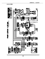
Page 31: ...APPENDIX ANNEXE APPENDIX ANNEXE APPENDIX ANNEXE APPENDIX ANNEXE APPENDIX ANNEXE V V V V V 25 30 35 POWER 25 30 35 POWER 25 30 35 POWER 25 30 35 POWER 25 30 35 POWER ...

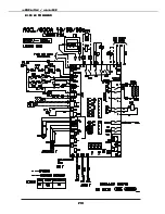
Page 32: ...APPENDIX ANNEXE APPENDIX ANNEXE APPENDIX ANNEXE APPENDIX ANNEXE APPENDIX ANNEXE V I V I V I V I V I 25 30 35 COMMAND 25 30 35 COMMAND 25 30 35 COMMAND 25 30 35 COMMAND 25 30 35 COMMAND ...

Page 33: ...APPENDIX ANNEXE APPENDIX ANNEXE APPENDIX ANNEXE APPENDIX ANNEXE APPENDIX ANNEXE V I I V I I V I I V I I V I I 40 50 60 POWER 40 50 60 POWER 40 50 60 POWER 40 50 60 POWER 40 50 60 POWER ...

Page 34: ...APPENDIX ANNEXE APPENDIX ANNEXE APPENDIX ANNEXE APPENDIX ANNEXE APPENDIX ANNEXE VIII VIII VIII VIII VIII 40 50 60 COMMAND 40 50 60 COMMAND 40 50 60 COMMAND 40 50 60 COMMAND 40 50 60 COMMAND ...

Page 35: ...LAZIONE DEL SISTEMA DI TRA REGOLAZIONE DEL SISTEMA DI TRA REGOLAZIONE DEL SISTEMA DI TRATT TT TT TT TTAMENT AMENT AMENT AMENT AMENTO DELL O DELL O DELL O DELL O DELL ARIA ARIA ARIA ARIA ARIA AJUSTE DEL SISTEMA AEROLICO AJUSTE DEL SISTEMA AEROLICO AJUSTE DEL SISTEMA AEROLICO AJUSTE DEL SISTEMA AEROLICO AJUSTE DEL SISTEMA AEROLICO Pulley close 0 round Poulie fermé 0 tour Riemenscheibe 0 Umdrehung ge...

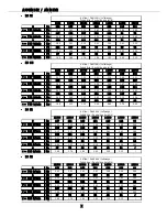
Page 36: ... 76 1 84 1 92 2 05 2 13 Air flow Débit d air Luftmenge Porta d aria Caudal de aire m h 30 PE 1200 12500 13000 13500 14000 14500 15000 0 Pa 232 226 215 204 178 159 146 v 897 tr min Kw 3 07 3 22 3 38 3 61 3 76 3 88 4 01 1 Pa 203 194 185 176 150 138 127 v 862 tr min Kw 2 80 3 05 3 17 3 38 3 45 3 67 3 86 2 Pa 183 176 164 153 138 125 111 v 820 tr min Kw 2 57 2 79 3 00 3 11 3 29 3 40 3 53 3 Pa 163 151 1...

Page 37: ... 86 1 99 2 13 2 25 2 35 Air flow Débit d air Luftmenge Porta d aria Caudal de aire m h 35 PE 40 PE 13000 13500 14000 14500 15000 15500 0 Pa 227 216 193 174 161 146 v 899 tr min Kw 3 49 3 72 3 88 3 96 4 09 4 22 1 Pa 197 188 162 150 139 122 v 860 tr min Kw 3 29 3 49 3 58 3 88 3 97 4 11 2 Pa 176 165 151 138 124 109 v 822 tr min Kw 3 11 3 23 3 40 3 52 3 63 3 95 3 Pa 154 142 130 119 109 97 v 787 tr min...

Page 38: ...7 3 47 3 57 3 69 3 80 Air flow Débit d air Luftmenge Porta d aria Caudal de aire m h 50 PE 60 PE 17500 18000 18500 19000 19500 20000 21500 0 Pa 238 227 219 208 196 188 177 v 1120 tr min Kw 6 55 6 74 6 88 7 02 7 18 7 30 7 55 1 Pa 221 211 202 179 167 153 145 v 1078 tr min Kw 6 01 6 27 6 39 6 50 6 87 7 01 4 22 2 Pa 192 181 170 155 141 129 122 v 1034 tr min Kw 5 20 5 49 5 60 5 88 6 31 6 69 6 90 3 Pa 1...

Page 39: ... chauffante de sécurité de l échangeur à plaque LPT Prise de pression ligne liquide LT Bouteille de réserve LWTS Sonde de T sortie d eau M I voyant liquide CPE Egalisation de pression compresseur PHE Echangeur à plaques SL Ligne d aspiration compresseurs TEV Détendeur thermostatique V4V Vanne d inversion C1 Compressor 1 C2 Compressor 2 CPT Condensing Pressure Tap DF Drier Filter DL Discharge Line ...

Page 40: ...EXE APPENDIX ANNEXE X I V X I V X I V X I V X I V TEV AIR FPC SL C 1 CPE C 2 D L HPP CPT D F M I EPT FPE LPT LWTS EWTS HR P H E AQCL AQCL AQCL AQCL AQCL AQCH AQCH AQCH AQCH AQCH CPE C 1 CPT SL D L HPP EPT FPC V4V TEV LT M I D F FPE LPT P H E LWTS HR EWTS AIR C 2 ...

Page 41: ... assemblied for 25 30 35 SV Safety Valve WPG Water pressure tap AP Automatic air purge valve CV Cut off valve DP Differential Pressure sensor only 25 30 35 models DU Drain off valve EAV Manual adjustment valve ET Expansion Tank EWC Entering water connection EWTS Entering Water Temperature Sensor FC Flexible joint FS Flow Switch only 40 50 60 models HR Evaporator Safety Heater LWC Leaving water con...

Page 42: ...ION CLIMA TION CLIMA TION CLIMA TION CLIMATISA TISA TISA TISA TISATION DE CONFOR TION DE CONFOR TION DE CONFOR TION DE CONFOR TION DE CONFORT T T T T Volumes calculés aux conditions de fonctionnement Eurovent air 35 C eau 12 7 C avec ratio de 2 5 l kW Pour d autres conditions nominales d utilisation recalculer le volume minimum en multipliant la puissance frigorifique correspondante par le ratio 2...

Page 43: ... CONFOR TION DE CONFORT T T T T Limitation linked to the volume of the expansion tank in the unit In the case of an installation with a water volume higher than the values stated in the above table an additional buffer tank should be included in the installation Limitation liée au volume du vase d expansion dans l unité Dans le cas d une installation avec un volume d eau supérieur aux valeurs anno...

Page 44: ...DEL REGOLAZIONE DEL REGOLAZIONE DEL REGOLAZIONE DEL REGOLAZIONE DEL AJUSTE DEL AJUSTE DEL AJUSTE DEL AJUSTE DEL AJUSTE DEL 1 Conditions Eurovent eau 12 7 C air 35 C 2 Avec Dt eau 7 5 K sur la puissance nominale 3 Avec Dt eau 3 K sur la puissance nominale AVAILABLE PRESSURE AVAILABLE PRESSURE AVAILABLE PRESSURE AVAILABLE PRESSURE AVAILABLE PRESSURE PRESSION DISPONIBLE PRESSION DISPONIBLE PRESSION D...

Page 45: ... 150 200 250 0 40 0 60 0 80 1 00 1 20 1 40 1 60 1 80 2 00 2 20 2 40 25 30 Water flow Débit d eau Wasserzufluß Flusso d acqua Caudal de agua l s 25 30 Nominal 1 1 04 1 29 Mini 2 0 7 0 86 Maxi 3 1 73 2 15 Water flow Débit d eau Wasserzufluß Flusso d acqua Caudal de agua l s 35 40 50 60 Nominal 1 1 6 1 75 2 16 2 75 Mini 2 1 07 1 16 1 45 1 8 Maxi 3 2 68 2 92 3 58 4 56 0 50 100 150 200 250 0 00 1 00 2 ...

Page 46: ... X X X X X X X X X AQCH AQCH AQCH AQCH AQCH 35 40 50 60 35 40 50 60 35 40 50 60 35 40 50 60 35 40 50 60 0 50 100 150 200 250 0 40 0 60 0 80 1 00 1 20 1 40 1 60 1 80 2 00 2 20 2 40 25 30 0 50 100 150 200 250 0 00 1 00 2 00 3 00 4 00 5 00 6 00 35 40 50 60 25 30 25 30 25 30 25 30 25 30 ...

Page 47: ...PERTE DE CHARGE SUR L EAU DES ECHANGEURS DE CHALEUR PERTE DE CHARGE SUR L EAU DES ECHANGEURS DE CHALEUR PERTE DE CHARGE SUR L EAU DES ECHANGEURS DE CHALEUR PERTE DE CHARGE SUR L EAU DES ECHANGEURS DE CHALEUR PERTE DE CHARGE SUR L EAU DES ECHANGEURS DE CHALEUR 35 40 50 60 35 40 50 60 35 40 50 60 35 40 50 60 35 40 50 60 0 00 50 00 100 00 150 00 200 00 250 00 0 00 0 50 1 00 1 50 2 00 2 50 3 00 3 50 2...

Page 48: ...APPENDIX ANNEXE APPENDIX ANNEXE APPENDIX ANNEXE APPENDIX ANNEXE APPENDIX ANNEXE XXII XXII XXII XXII XXII ...

Page 49: ...DESP 97 23 CEE MODULO A CATEGORIA I AQCL 25 30 35 AQCH 25 30 35 SOTTOMODULO A1 CATEGORIA II AQCL 40 50 60 AQCH 40 50 60 CON SUPERVISION POR EL TUV RHEINLAND 6 RUE HALÉVY 75 009 PARIS FRANCE I PRODOTTI SONO FORNITI CON LA MARCATURA DI CONFORMITE CE 0035 DIRECTIVA MAQUIAS 98 37 CEE DIRECTIVA BAJA TENSION DBT 73 23 CEE ENMENDATA POR LA DIRECTIVA 93 68 CEE DIRECTIVA COMPATIBILIDAD ELECTROMAGNETICA 89 ...

Reviews: