background image


Printed on 23 May, 2011 

Manual # 99903184 

14K160TH OTR Body & Air 

Compressor 

Commander IV OTR Body & Compressor Parts - Specifications - Instructions 

Revised 20110519 


IOWA MOLD TOOLING CO., INC.


PO Box 189 

Garner, IA 50438 

Tel: 641-923-3711    FAX: 641-923-2424 

Website: http://www.imt.com 


Copyright © 2011 Iowa Mold Tooling Co., Inc. 

All rights reserved 

No part of this publication may be reproduced, stored in a retrieval system, or transmitted in any 

form or by any means, electronic, mechanical, photocopying, recording or otherwise without the 

prior written permission of Iowa Mold Tooling Co., Inc. 

Iowa Mold Tooling Co., Inc. is an Oshkosh Corporation Company. 
 

Summary of Contents for 14K160TH

Page 1: ...41 923 3711 FAX 641 923 2424 Website http www imt com Copyright 2011 Iowa Mold Tooling Co Inc All rights reserved No part of this publication may be reproduced stored in a retrieval system or transmit...

Page 2: ......

Page 3: ...5 22 Body Assembly 51715799 6 23 DAR130 Compressor Specifications 25 Compressor Safety 29 Compressor Precautions 30 Compressor Safety 31 Compressor Warning Decals 33 Compressor Instruction Decals 35...

Page 4: ...Oil Schematic 61 Hydraulic Schematic 62 Oil Cooler 63 Hose Ports 65 Compressor Air Inlet System 66 Compressor Discharge System 67 Compressor Electrical System 70 Wiring Diagram 71 Compressor Mounting...

Page 5: ...mon sense while operating and maintaining the crane and follow all safety procedures and regulations Treat this equipment with respect and service it regularly In addition to reading the manual become...

Page 6: ...ntenance of the crane If questions arise contact IMT or your IMT distributor for clarification WARRANTY Warranty of this unit will be void on any part of the unit subjected to misuse due to overloadin...

Page 7: ...RTS Fan sensor 302899 20090105 51715799 ECN 10854 New body weldment drawings 20090305 51715799 3 ECN 10854 New drawing for page 3 20090423 51715799 1 ECN 10938 Update body lights to LED 20090526 COMPR...

Page 8: ......

Page 9: ...ge Assembly 51715800 2 12 OTR Package Assembly 51715800 3 13 OTR Package Assembly 51715800 4 14 OTR Package Assembly 51715800 5 15 Body Assembly 51715799 1 16 Body Assembly 51715799 2 17 Body Assembly...

Page 10: ...as not being Critical or Normal Wear items during the first year of operations and you need to contact the distributor or manufacturer for availability ASSEMBLY PART PART NO DESCRIPTION QTY CODE 5171...

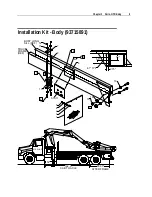
Page 11: ...ts OTR Body 9 Installation Kit Body 93715891 16 2 75 13 6 5 5 5 81 TYP 6 15 16 5 4 2 3 1 9 10 11 12 13 12 11 7 8 25 1 2 3 4 5 3 BODY LONG SILL REF TRUCK FRAME REF 85 33 AFTER FRAME 192 0 CAB TO AXLE 5...

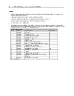
Page 12: ...PLY TORQUE TO THE NUT BOLTS MAY PASS THROUGH FRAME IN EITHER DIRECTION 93715891 PARTS LIST ITEM PART DESCRIPTION QUANTITY 1 76393799 MUD FLAP 2 2 72063001 WASHER 1 4 WRT 8 3 72060025 CAP SCR 5 16 18X1...

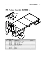
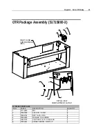
Page 13: ...T REF 1 2 3 VIEW A 4 5 7 6 A 51715800 PARTS LIST ITEM PART DESCRIPTION QUANTITY 1 70731371 HOSE GUIDE ROLLER ASM 2 2 72060004 CAP SCR 1 4 20X1 HHGR5 4 3 72062104 NUT 1 4 20 LOCK 4 4 51715799 BODY ASM...

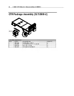
Page 14: ...99903184 OTR Package Assembly 51715800 2 1 2 4 VIEW B 3 B 51715800 2 PARTS LIST ITEM PART DESCRIPTION QUANTITY 1 70733434 HOSE REEL 1 2X50 2 2 72060047 CAP SCR 3 8 16 X 1 1 4 HHGR5 8 3 72062103 NUT 3...

Page 15: ...OUT 8 8 9 7 6 5 7 RIGHT HAND COMPARTMENT REF 3 1 4 2 51715800 3 PARTS LIST ITEM PART DESCRIPTION QUANTITY 1 51715850 FRL 1 2 72060004 CAP SCR 1 4 20X1 4 3 72062104 NUT 1 4 20 LOCK 4 4 76392820 WASHER...

Page 16: ...31547 BARB NIPPLE 1 2MPT 3 4HOSE BRS 2 8 72066000 HOSE CLAMP SAE12 2 9 89393634 HOSE 100R4 3 4X25 1 OTR Package Assembly 51715800 4 FRL REF 1 2 1 HOSE REEL REF 3 1 1 51715800 4 PARTS LIST ITEM PART DE...

Page 17: ...PTION QUANTITY 1 72053556 STREET ELBOW 3 4NPT 90 3 2 72053558 ADAPTER 3 4MPT 3 4MPT HEX 1 3 73054230 BALL VALVE 3 4NPT 1 4 72053458 BARB NIPPLE 3 4MPT 3 4HOSE BRS 1 5 72066000 HOSE CLAMP SAE12 2 6 893...

Page 18: ...PARTS LIST ITEM PART DESCRIPTION QUANTITY 1 52718265 BODY 1 2 60122496 DOOR WLDMT 24 00H X 27 75W 2 3 72661357 HINGE BUTT 4 NB ZC 50 PIN 4 4 60122663 BRACKET HINGE COMMANDER IV STEP 2 5 52716189 WLDM...

Page 19: ...9 4 14 76393636 GROMMET RUBBER 2 00 9 23 72661384 RIVET AL LG HD 25X 50 GRIP 96 24 76393253 GASKET LATCH W STUDS 2 25 60030324 SPACER 1 38 X 1 50 X 62 COMMANDER DOOR 2 26 72063166 WASHER SS 25 R WRT 1...

Page 20: ...MET TAIL LIGHT 6 16 77040180 LIGHT BACKUP 2 17 77040493 LIGHT STOP TURN TAIL LED 4 4 20 77040006 LIGHT LICENSE PLATE 2 21 51715985 KIT LICENSE PLATE HARDWARE 1 22 60350058 TREAD SHUR STEP 12in X 26in...

Page 21: ...2661269 HANDLE GRAB CHROME 16L 3H 819 1 76 71413562 WHEEL 50 X 4 00 NYLON 1 77 71413563 PLATE RH HEAD ASM 1 78 71413564 PLATE LH HEAD ASM 1 79 71413565 COUNTER BALANCE ROLLER 1 80 71413566 TRACK VERT...

Page 22: ...EACH END 9 PULL NAIL ON THE COUNTERBALANCE ROLLER THIS WILL CREATE TENSION TO HELP THE DOOR ROLL UP 10 INSTALL THE VERTICAL RAILS 80 LEAVE DOOR DOWN A FEW INCHES AND ANGLE DOOR BACK ENOUGH TO ALLOW V...

Page 23: ...Y 31 70733807 DRAWERS PAINTED 26W 2 3in 1 5in 42 62X17 5 1 32 52716191 WELDMENT SHELF FRONT LH COMPT COMMANDER IV 1 33 52716192 WELDMENT SHELF FRONT LH COMPT COMMANDER IV 1 34 60030316 STOP UHMW COMMA...

Page 24: ...77040384 LIGHT COMPARTMENT 12V 2 1AMP 6 52 76395950 MAT RUBBER 3 9 FT 53 60122686 ANGLE DOOR PROTECTOR COMMANDER IV 1 54 52716198 DIVIDER SHELF UNDER BODY TOOLBOX W HANGER BRACKET 1 55 60122685 SHELF...

Page 25: ...T DIMENSIONS 24 63 2 34 5 NOTE 1 INSTALL ITEM 4 INSIDE BOTTOM OF COMPARTMENT MAKE SURE TO BUTT FACTORY EDGES TOGETHER 51715799 6 PARTS LIST ITEM PART DESCRIPTION QUANTITY 63 76393340 MAT RUBBER 38X 24...

Page 26: ......

Page 27: ...ITY COMPRESSOR not hydraulic 3 75 gallons 14 2 liters MOUNTED COMPRESSOR DIMENSIONS 27 686 mm from back of mounting surface to front of compressor 94 25 2394 mm overall width COMPRESSOR AIR INLET 10 w...

Page 28: ...4K160TH OTR Body Air Compressor Manual 99903184 Compressor Dimensions Shown Mounted in Bulkhead 686 mm 27 2394 mm 94 25 Bulkhead 10001 CMMDR 24V Compressor Assembly 229 9 229 9 229 9 1555 mm 60 8 178...

Page 29: ...mm 27 2394 mm 94 25 Air Filter Inlet Control Valve Oil Cooler Oil Air Cooler 83 3 l 22 gal Air Tank Sump Oil Filter Element Coalescer Spin On Element Hydraulic Motor Bulkhead Air Drive Shaft Air End O...

Page 30: ......

Page 31: ...is Chapter Compressor Precautions 29 Compressor Safety 31 Compressor Warning Decals 32 Compressor Instruction Decals 35 Compressor Terminology 35 Description of Components 36 C H A P T E R 4 Compresso...

Page 32: ...rts Hot oil under pressure can cause severe injury or death Shut down let cool and relieve pressure in compressor before servicing All electrical components and cable wiring must be installed and grou...

Page 33: ...ttempt to service any part while the machine is operating WARNING AVOID PERSONAL INJURY OR PROPERTY DAMAGE Check the compressor sump oil level only when the compressor is not operating and the system...

Page 34: ...ressor unit Do not leave tools rags or loose parts on the compressor or drive parts Do not use flammable solvents for cleaning parts Keep combustibles out of and away from the compressor and any assoc...

Page 35: ...the vehicle after it has been painted trimmed and undercoat etc and prior to being put into service The decals shall be placed so as to be clearly visible to the user and service personnel Figure 1 P...

Page 36: ...34 14K160TH OTR Body Air Compressor Manual 99903184 Figure 4 Place on body near compressor mounting foot...

Page 37: ...of compressed air being produced expressed as cubic feet of air per minute COMPRESSOR LUBRICANT IMT blue lube GPM Refers to the gallons per minute of hydraulic fluid flowing through the pump OIL SUMP...

Page 38: ...ted into the compressor The oil lubricates the rotating parts and bearings serves as a cooling agent for the compressed air and seals the running clearances LUBRICATION SYSTEM Oil from the compressor...

Page 39: ...element type It has a built in safety bypass COMPRESSOR COOLING SYSTEM The compressor cooling system consists of a combination aftercooler and oil cooler remote mounted on the common frame Compressor...

Page 40: ...ply to air demand and to prevent excessive discharge pressure when compressor is at idle Control of air delivery is accomplished by the inlet valve regulation and modulation as directed by the dischar...

Page 41: ...eases the receiver pressure rises When this pressure exceeds the set point of the pressure regulator the regulator opens sending a secondary pressure signal to the inlet valve The poppet valve moves t...

Page 42: ......

Page 43: ...art 41 Lubricant Recommendations 43 Commander IV Compressor Preventative Maintenance Kit 44 Compressor Maintenance Procedure 45 47 Compressor Troubleshooting 49 Compressor Recommended Spare Parts 51 C...

Page 44: ...HRS MONTHLY 1 Drain water from compressor oil EVERY 100 HRS 1 Grease compressor drive shaft if applicable EVERY 500 HRS 6 MONTHS 1 Change compressor oil and oil filter 2 Check compressor shaft seal fo...

Page 45: ...ty lubricant must rest with the individual supplier if they choose not to use the recommended IMT rotary screw lubricant The lubricant supplier s recommendation must therefore be based upon not only t...

Page 46: ...and use lubricant wisely Commander IV Compressor Preventative Maintenance Kit 91716201 PREVENTATIVE MAINTENANCE KIT PART DESCRIPTION QUANTITY IN KIT FREQUENCY 301669 COALESCER LONG SPIN ON ELEMENT 1...

Page 47: ...or break any connection in the air or oil system AIR INTAKE FILTER The air intake filter is a heavy duty two stage dry type high efficiency filter designed to protect the compressor from dust and fore...

Page 48: ...rely when tightening the hose fitting OIL RETURN LINE This line originates at the bottom of the air oil coalescer and flows through a 1 4 hose elbow located at the air end On the DAR130 Rotary Screw C...

Page 49: ...SHAFT SEAL INSTALLATION 1 Remove all hoses and fittings from the compressor unit including 1 2 discharge line 3 4 main oil injection 1 4 regulator 1 4 blowdown and 3 air intake 2 Strap compressor unit...

Page 50: ...irt ring retainer once the new seal and cover assembly are in place 13 Place seal cover against rotor casting Do not damage the seal Slide off assembly tool 14 Screw down the socket head retaining bol...

Page 51: ...off the engine take the vehicle for service Unplanned Shutdown Engine problem Check fuel level truck dash gauges and indicators Check compressor discharge temperature switch gauge If the relay circuit...

Page 52: ...mp Pressure Does Not Blow Down Inoperative automatic blow down valve at coalescer head Replace valve Blockage Check air line from side of inlet valve to blow down valve Clogged muffler Check clean muf...

Page 53: ...ly IMT approved compressor oil Dirty oil change oil Oil return line plugged Clean oil return line Change oil and oil filter per maintenance schedule Compressor air inlet Check system for leaks High Co...

Page 54: ...COMPRESSOR COMPONENTS 301669 SPIN ON COALESCER 1 P 300005 001 OIL FILTER ELEMENT 2 P 301921 FAN ASSEMBLY 12V 1 W 303185 FAN ASSEMBLY 24V 1 W 300057 REGULATOR VALVE 1 W 301827 BLOW DOWN VALVE 1 W AIR...

Page 55: ...FAN SENSOR 100 1 W 302024 COIL 1 W 302025 SOLENOID 1 W 302026 RELIEF MANIFOLD 1 W 301834 NORMALLY OPEN PRESSURE SWITCH 20 1 W 302028 SHAFT SEAL REMOVAL TOOL T10G 1 P 302030 HYD MOTOR SEAL KIT 1 W 3016...

Page 56: ......

Page 57: ...dure Decal 301476 Start Up 1 Set brakes per company procedure Chock wheels 2 Check compressor oil level Add oil if low 3 Depress clutch Engage PTO 4 Put transmission in neutral 5 Let out clutch Depres...

Page 58: ...sengaged and the vehicle is parked on level ground PRESSURE RELIEF VALVE Vents sump pressure to the atmosphere if the pressure inside the sump exceeds 200 PSI COMPRESSOR INLET CONTROL VALVE Regulates...

Page 59: ...dblasting equipment or an air storage tank use a check valve directly after the minimum pressure orifice to prevent backflow into the sump This check valve should have a maximum pressure drop rating o...

Page 60: ...uch that the pressure gauge reads between 100 and 140 psi This ensures that the oil temperature has had adequate time to come up to operating temperature and that most of the water in the system has b...

Page 61: ...oler 63 Hose Ports 64 Compressor Air Inlet System 66 Compressor Discharge System 67 Compressor Electrical System 69 Wiring Diagram 70 Compressor Mounting System 72 Air Tank 74 Murphy Latching Relay Re...

Page 62: ...ONTROL 1 3 301992 COOLER OIL 18 6 X 27 1 4 301804 COOLER OIL AIR 1 5 300225 SUMP 12 DISCHARGE WITH PLATE BAFFLE 1 6 302013 ASSEMBLY AIR FILTER 1 7 302003 FRAME 1 8 301669 COALESCER SPIN ON ELEMENT 1 9...

Page 63: ...Oil Schematic 3 4 OIL HOSE 1 4 TUBING TO PRESSURE GAUGE 1 1 2 AIR 3 4 AIR AFTERCOOLER IN OIL HOSE OUTLET ON OPPOSITE SIDE 1 4 TUBING BLOWDOWN 1 4 TUBING OIL RETURN 1 4 TUBING REGULATED 1 4 TUBING 3 4...

Page 64: ...OSE 3000 PSI MINIMUM CRIMP FITTINGS BY INSTALLER 1 ID MINIMUM PRESSURE FEED HOSE 3000 PSI MINIMUM HYDRAULIC PUMP NORMALLY OPEN HYDRAULIC SOLENOID RELIEF BLOCK 80024 SHUT OFF VALVE 10 25 MICRON RETURN...

Page 65: ...OLT WHIZLOCK GR5 5 16 18 X 1 29 3 301813 SHROUD OIL AIR COOLER 1 4 302008 BRACKET HYD COMBO MOUNTING 1 5 301992 COOLER OIL 18 6 X 27 1 6 960216 100 ELBOW HYDRAULIC 1 MJIC X 1 MNPT 2 7 302005 BRACKET O...

Page 66: ...EM PART DESCRIPTION DETAILS QUANTITY 13 925305 283 NUT WHIZ LOCK 5 16 18 17 14 301804 COOLER OIL AIR 18 6 1 15 300989 FAN ASSEMBLY WITH MOTOR GRILL 2 16 302017 SHROUD OIL COOLER 18 88 X 27 0 1 17 9602...

Page 67: ...no demand for air i e Closed service valve or air pressure dead headed into a tool that is not being used Maximum pressure in this line is 50 PSIG B1 Air signal from B regulator outlet to compressor i...

Page 68: ...ER MOUTING 1 2 302015 BAND AIR FILTER MOUNTING 1 3 302013 ASSEMBLY AIR FILTER 1 4 300031 CAP AIR FILTER 1 5 70048222 INDICATOR AIR FILTER 25 H2O 1 6 301786 300 CLAMP AIR INLET 3 2 7 301785 300 HOSE AI...

Page 69: ...pressor Discharge System 43 44 51 1 3 4 2 53 5 54 47 58 7 6 3 24 30 31 29 28 25 7 27 26 45 40 41 42 40 41 42 13 15 14 46 47 48 11 40 41 42 42 9 12 18 55 49 23 22 21 20 19 8 50 30 59 17 57 32 56 16 33...

Page 70: ...PT 1 20 73540110 VALVE BLOWDOWN 1 4 N C 1 21 60124689 MUFFLER EXHAUST 1 4 1 22 960204 025 ELBOW HYDRAULIC 1 4 MJIC X 1 4 MNPT 1 23 73540109 VALVE REGULATOR 1 4 1 24 902206 026 TEE PIPE REDUCER 1 1 2 X...

Page 71: ...MJIC X 1 4 MNPT 1 50 300845 VALVE MINIMUM PRESS 3 4 1 51 302287 BRACKET COALESER SUPPORT 1 52 902915 010 PLUG PIPE 1 4 RECESSED ZINC 2 53 72053404 PLUG PIPE 1 2 RECESSED ZINC 1 54 984724 188 PLUG 24...

Page 72: ...ARTS ITEM PART DESCRIPTION DETAILS QUANTITY 1 300074 GAUGE HOURMETER 1 2 301755 012 RELAY POWER 12VDC 4 3 929104 075 BOLT HEX GR5 1 4 20 X 3 4 4 4 924304 145 NUT NYLOC GR5 1 4 20 4 5 302139 004 SWITCH...

Page 73: ...MBLY LESS TERMINALS 12065686 WIRE KIT WIRE KIT COMPRESSOR OIL AND AFTERCOOLER HYDRAULIC COOLER NORMALLY OPEN HYD OIL SENSOR 88 C 190 F NORMALLY OPEN HOURMETER AIR PRESSURE SWITCH MOUNT AT COALESCER CO...

Page 74: ...ESSOR PARTS MOUNTING SYSTEM ITEM PART DESCRIPTION DETAILS QUANTITY 1 302003 FRAME 1 2 302045 BRACKET HYDRAULIC VALVE BLOCK MOUNTING 1 3 300724 MOTOR HYDRAULIC 1 4 302006 BRACKET COMPRESSOR MOUNTING 1...

Page 75: ...0 961902 012 TEE MB 1 8 F X 1 8 F X 1 8 M 1 31 301421 SWITCH PRESSURE NORMALLY CLOSED 1 32 902915 005 PLUG PIPE 1 8 RECESSED ZINC 1 33 970416 131 ELBOW HYDRAULIC 1 MJIC X 16 MSAE 1 34 80024 KIT HYDRAU...

Page 76: ...13 TANK AIR 22 GALLON VERTICAL 22 GAL VERTICAL 1 2 938206 071 WASHER FLAT GR8 3 8 4 3 937806 094 WASHER LOCK GR8 3 8 4 4 960212 075 ELBOW 3 4 JIC X 3 4 MNPT 1 5 960112 075 CONNECTOR 3 4 MJIC X 3 4 MNP...

Page 77: ...5 Murphy Latching Relay Retrofit Kit 99903400 WITH MURPHY RELAY 8 3 4 2 2 3 1 5 2 WITH MURPHY RELAY 6 2 7 2 1 FROM TERMINAL 87A OF OLD SHUTDOWN RELAY FROM TERMINAL 85 OF OLD SHUTDOWN RELAY FROM TERMIN...

Page 78: ...TEMP SHUTDOWN 1 4 72060002 CAP SCR 1 4 20 X 3 4 2 5 72063001 WASHER 1 4 FLAT 2 6 72063049 WASHER 1 4 LOCK 2 7 72062104 NUT 1 4 20 HEX 2 8 77040000 RING TERMINAL 3 9 77040048 BUTT TERMINAL NS 3 10 7014...

Page 79: ...gauge Look at the back of the switchgauge and find the black wire this wire will connect to terminal 85 of the shut down relay If the black wire can not be followed visually a continuity test can be...

Page 80: ...es to the relay The wire that was connected to terminal 30 of the shutdown relay will now connect to the B terminal of the Murphy relay The wire that was connected to terminal 85 of the shutdown relay...

Page 81: ...osts on the front of the Murphy temperature gauge to the chrome bezel When the contact is shorted across the latching relay will trip and the compressor will stop running Reset the latching relay by p...

Reviews: