background image

User Manual

Summary of Contents for 104441-01

Page 1: ...User Manual...

Page 2: ...of Symbols Warning Dangerous operations that may damage the devices or causes personal injury Caution Operations may cause the device software to not oper ate normally and or cause injury Note Importa...

Page 3: ...lignment 23 Using the Testing Dummy 23 Zeroing the Sensor Prior to Data Collection 24 05 Software Overview Startup 26 Basic Operations 27 Pairing the Sensor and DCM 27 Setting System Preferences 29 Ch...

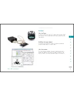
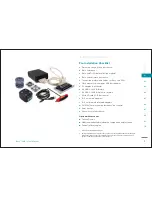
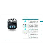
Page 4: ...System Overview 01...

Page 5: ...rate measurements of 3 axis forces and moments experienced by a lower limb prosthesis user in any environment without wires or the need for additional lab equipment Con guration and installation of th...

Page 6: ...acting on the device and residual limb DCM Data Collection Module The sensor communicates with the PC software through this module while operating in wireless mode iPecs Lab Software This is an inter...

Page 7: ...B 5 pin mini B cable J MicroSD card 2GB not shown K 2 4 hole male adapters2 L 2 4 hole female rotatable adapters2 M 16 M6x14mm mounting fasteners2 not shown N 4mm hex key O Sensor xture not shown Opti...

Page 8: ...of the co ordinate system used to measure forces and moments data Zero Button This button has the same function as the Zero button in the software Reference the Pairing the Sensor and DCM in the M So...

Page 9: ...C Auxiliary Port Enables connection of external sensors to the iPecs Lab sensor allowing the test subjects data to be time synchronized with iPecs data and sent wirelessly to the iPecs Lab software o...

Page 10: ...Pecs Lab sensor is battery powered and the DCM is powered through the user s PC Sensor has an automatic low power sleep mode for extending use System Overview Force and Moment Data UNITS Fx Fy Fz Mx M...

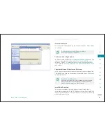
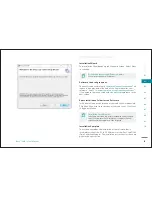
Page 11: ...Software Installation 02...

Page 12: ...your computer it will guide you through the following steps If Autorun is not enabled point to Start click on t t My Computer and double click on the r Install CD The les on the CD are as follows iPe...

Page 13: ...on Next to advance to the t next screen Select Installation Folder for the Software In the next screen a con rmation of your selections is requested Click Back if you want to review any of your selec...

Page 14: ...re as follows iPecs Lab Install Folder install le setup exe LM_USB_Drivers folder containing the USB driver les yymmdd Analog Interface Calibration xls yymmdd iPecs User Manual pdf Axx Calibration Mat...

Page 15: ...ck on Next to advance to the t next screen Select Installation Folder for the Software In the next screen a con rmation of your selections is requested Click Back if you want to review any of your sel...

Page 16: ...USB Driver Installation 03...

Page 17: ...CD and click Next In the next screen select t t Install from list or a speci c location Advanced and click Next t t Installation Options The wizard will then search for the software in the CD and ins...

Page 18: ...installation CD In the next install window Windows will read the CD to look for drivers Complete Installation Windows will proceed to nd and install the driver The installation will take a while depe...

Page 19: ...order s to enable a complete search To continue click OK then K Next t t Windows will then install the required driver les A notice window will appear during installation notifying the user Windows c...

Page 20: ...Hardware Installation 04...

Page 21: ...the Lithium ion batteries in the iPecs Lab sensor Keeping the battery fully charged is bene cial to the battery life Assemble Mounting Adapters to the Sensor The sensor requires two 4 hole mounting ad...

Page 22: ...ver compress the outer cover and severely damage the sensor Always attach to the sensor xture STEP 1 Place the xture into a vice or rigid constraint with the prongs facing upward STEP 2 Fit the iPecs...

Page 23: ...operly Endoskeletal alignment of a prosthetic device should always be performed by a certi ed prosthetist Using the Testing Dummy The testing Dummy is an optional tool that allows you to tempo rarily...

Page 24: ...heir prosthetic limb STEP 1 Stand the prosthesis vertically on a level surface it cannot be leaning or on its side this method may not be ideal for above knee prosthetic limbs STEP 2 Zero out the sens...

Page 25: ...Software Overview 05...

Page 26: ...o start the iPecs Lab program go to Start Menu Pro grams College Park Industries iPecs Lab STEP 2 The program opens with a Login screen Choose User as the Login Type leave the password eld blank and c...

Page 27: ...d DCM need to be paired to start data acquisition and display readings Begin by clicking on the Connect to iPecs button just above the grid lines in the iPecs Lab software window By clicking the butto...

Page 28: ...mpling the data at a high rate of speed It can sample each of the strain gages and send the data to the PC at over 1000 samples sec If the sample rate does not need to be that high the sensor can aver...

Page 29: ...m force meter Distance inch foot meter centimeter millimeter Set the unit preferences before collecting data Units cannot be changed in the iPecs Lab software after data collection begins Preferences...

Page 30: ...t select Edit from the menu bar and click on t Channels This brings up the following Channels window where the user s can select options to customize the appearance of the plots in the main iPecs Lab...

Page 31: ...Recording Data 06...

Page 32: ...a Save File window Select the location and name of the le to save the data points appearing on the screen The default extension for the le is txt plain text le t Once the le name is entered click on...

Page 33: ...s in the main program window then select s File in the e menu bar and click on Playback Streaming File This will bring up a File Selection window where the user can se lect a le and this le will be pl...

Page 34: ...Uninstalling Software 07...

Page 35: ...on the Start menu and select u Control Panel In the Control Panel click on Add or Remove Programs link to s bring up the list of programs installed on the PC From this list select iPecs Lab applicati...

Page 36: ...ing click on s Uninstall a program link This will bring up the list of programs installed on the PC From this list double click on iPecs Lab application b Windows will show a dialog box requesting aut...

Page 37: ...Uninstalling USB Driver 08...

Page 38: ...elect the Hardware tab at the top of the window e STEP 2 Click on Device Manager to see a list of Hardware Pe r ripherals connected to your system internal and external STEP 3 Under Ports COM LPT righ...

Page 39: ...a list of Hardware Pe r ripherals connected to your system internal and external Uninstalling USB Driver STEP 3 Under Ports COM LPT right click on Luminary Micro USB serial port COM xx and select Uni...

Page 40: ...System Calibration 09...

Page 41: ...potential loss of accuracy However ad vantages to this approach are additional control of sampling rates and synchronizing of strain data with data from other sources such as force plates In this case...

Page 42: ...ion Procedure STEP 1 Complete wire connections from the iPecs Lab DCM to the customer equipment using the provided connection protocol cables and short jumper wires Shielding these jumpers using GND i...

Page 43: ...ow click the Connect to sensor button on the toolbar r STEP 6 Use the Command control to select Test Pattern High from the drop down menu Click the Command control d button Send to cause the test sele...

Page 44: ...between channels represent analog circuit errors DCM Customer DCM System Analog Readings Volts Scale Factor Multiplier Zero Offset Volts SIGNAL NAME J3 Pin Pin Wire DCM Low Output DCM High Output iPe...

Page 45: ...EP 10 Enter the scale factor and zero offset values into the researcher s data acquisition system STEP 11 Turn the sensor OFF and exit the iPecs Lab software F STEP 12 To acquire forces and moments th...

Page 46: ...Troubleshooting 10...

Page 47: ...en LEDs turn on and off This resets the sensor s frequency to the default value and allows communication when the DCM is turned on Red LED above the Zero button is ON This indicates a general error in...

Page 48: ...the power button During times of inactivity the sensor that is running will enter a lower power Sleep Mode to save battery power If activity is detected in Sleep Mode the sensor will reactivate givin...

Page 49: ...Lab sensor is a non serviceable unit Contact College Park Industries Technical Support for software and hardware issues Environmental Use Do not expose the iPecs Lab System to the following temperatur...

Page 50: ...267 B 101105 17505 Helro Drive Fraser MI 48026 USA T 800 728 7950 F 800 294 0067 www college park com info college park com Copyright 2010 College Park Industries Inc All rights reserved...

Reviews: