MANUAL
– Subject to alteration! Version: August 2022
ipf electronic gmbh
│
Rosmarter Allee 14
-
58762 Altena
-
Germany │ Tel +49 2351 9365
-
0
-
info@ipf-
electronic.com
16
5.1.3
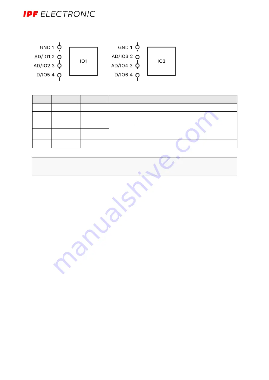
IO1 and IO2
Fig. 8: Schematic drawing of the IO1 and the IO2 interface
Pins
Signal IO1
Signal IO2
Description
1
GND 1
GND 1
Ground / 0 V / V-
2
AD/IO1
AD/IO3
Configurable in:
Analog or digital input
-or-
Digital output
3
AD/IO2
AD/IO4
4
D/IO4
D/IO6
Digital input or output
Specification of the digital output (IO1 to IO6)
•
Voltage drop is max. 1 V to the 24 V operating voltage
•
Max. Output current = 120 mA
•
Reverse polarity protected and protection against reverse current
Specifications of the digital input (IO1 to IO6)
•
Compliant with EN61131-2 Type1/3
•
Switching threshold between 5 V and 11 V
•
Pulldown current ~2 mA
•
Bandwidth < 100 kHz
•
Dielectric strength according to EN61131-2 30V
Note:
Whether a pin is addressed as analog input or as digital input or output must be
defined via the user software.


