MANUAL
– Subject to alteration! Version: August 2022
ipf electronic gmbh
│
Rosmarter Allee 14
-
58762 Altena
-
Germany │ Tel +49 2351 9365
-
0
-
info@ipf-
electronic.com
18
5.1.7
LED display
•
3 x bicolor LED (red/green) on the front side
5.2
BY000002 Connect to power supply
Prerequisite: The module is correctly mounted on the mounting rail. See
4.1 Mounting and dismounting
the module to/from the mounting rail
, page 13.
1.
For easier mounting, you can remove the connector with the terminal contacts from the
interface
24V DC.
WARNING
Incorrect voltage supply can lead to irreparable damage to property!
Note that the voltage supply corresponds to the parameter of 24
V ± 10 %.
2.
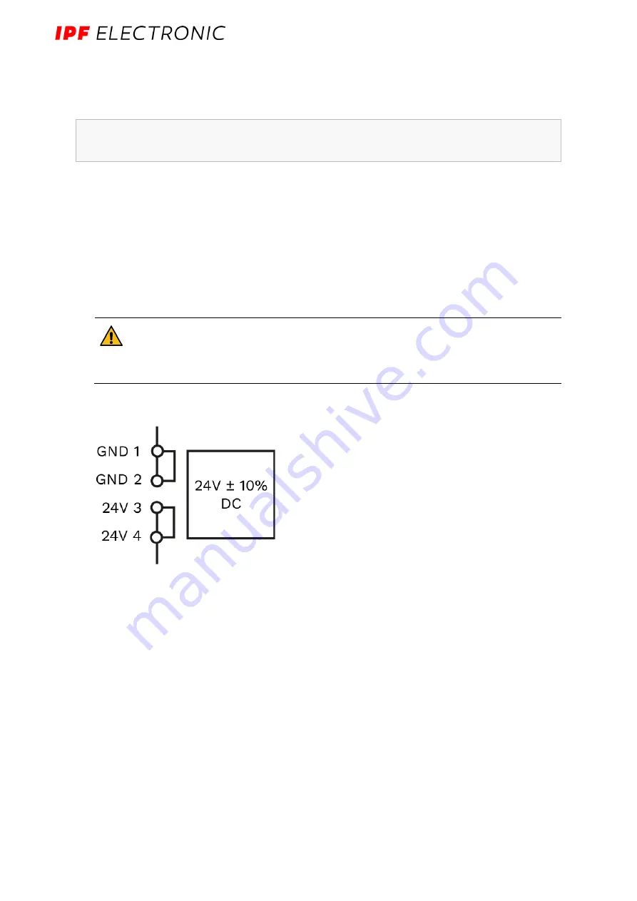
Clamp the cable tail of the power connection into the connector as shown in the
following diagram:
Fig. 9: Schematic drawing of the voltage supply
3.
If the operating voltage is correctly applied, the status LEDs light up on the front of
the module - depending on the configuration - and signal the booting of the SIINEOS
platform.
Note
: The LED lights and their status display are configured in the user software.
See also Chapter 3.3 LED display, page 12.


