Piping and Instruments Diagram
Page 22
Operating manual LC 340.01-A.3.5/6
Current revision status: Apr 4, 2019
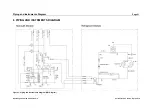
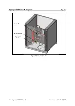
6.1 Refrigerant module
Figure 4: P&I Diagram refrigerant module
Component name
Electric designation
Measurement / Operation
Compressor 1
M1
Compressor 2
M2
Low pressure sensor
B9
Evaporating pressure
High pressure sensor
B10 (B15)
Condensing pressure
High pressure control
A13 (PS2)
Emergency cut-out @ 28 bar
Fan
M3
The compressors (M1 & M2) pull the low pressure refrigerant out of the evaporator.
The low pressure sensor (B9) monitors the pressure. If the evaporating pressure goes
lower than 3.9 bar, there is the danger of icing the water section of the heat exchanger.
To avoid this, the controller switches off the compressor. In this case the alarm
message
“Refrigerant Circuit / Low Pressure”
will be displayed.
The compressor increases the pressure of the refrigerant gas from evaporating
pressure to condensing pressure. During this process the refrigerant is superheated. If
any error causes the condensing pressure to go higher than 28 bar, the high pressure
switch (A13, PS2) will stop the chiller immediately. Such a failure is by definition, an
emergency shut off. Therefore this failure has to be reset manually at the high

