2-18
Using Your Device
Using the YLR-Series
Interlock Safety Circuit
YLR lasers include an Interlock Safety Circuit that uses a dual-channel system with
monitored output and manual reset.
When you open the Interlock, the safety circuit opens and power to the laser diodes
is removed.
Follow these steps:
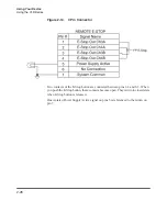
1. Close the dual channel interlock (on 24-pin connector: pin1 is connected with
pin4 and pin2 is connected with pin3). Otherwise, the internal main power
supply is switched off and the emission cannot be turned on.
Once any of the pairs of the mentioned above contacts is opened, you cannot
switch the lasers power supply on until the second pair is opened and then both
pairs are closed.
2. If you close the interlock (the Emergency Stop button is also released) and a
fault is not detected, press the
Start
button to connect the remote start contacts,
which enables the main power supply. The Power Supply (PS) Active signal
enters a high state and power is supplied to the laser module. The laser diodes
remain inactive until a separate Laser Enable signal transitions high and an
output power level set to a non-zero value.
The power to the laser diodes also turns on. However, under normal conditions
the diodes only turn on after emission is enabled.
When you open the interlock or a fault is detected, the laser diodes are discon-
nected from the main power supply. The Power Supply Active signal enters a
low state.
A detected fault is latched and circuits open the monitored manual reset loop,
thus preventing the laser from being restarted until the fault is addressed. If a
fault is detected, such as a shorted interlock channel, or a shorted
Start
button,
the safety circuit does not reset until the fault is corrected.
If the remote
Start
button is shorted (this is the equivalent of holding in the
Start
button), the circuit does not reset when the interlocks are closed until the safety
circuit processes both channels open and then closed or the power to the safety
circuit is cycled (with the Start button in the opened state in both cases).
Summary of Contents for QCW YLR-150
Page 4: ...ii Preface Audience...
Page 10: ...viii...
Page 30: ...1 20 Overview of the YLR Series Fiber Lasers Additional Safety Resources...
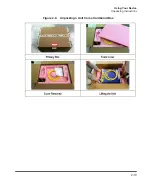
Page 43: ...2 13 Using Your Device Unpacking Instructions Figure 2 9 Unpacking a Unit from a Cardboard Box...
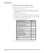
Page 45: ...2 15 Using Your Device Unpacking Instructions Figure 2 10 Unpacking a Unit from a Wooden Crate...
Page 57: ...2 27 Using Your Device Using the YLR Series Figure 2 13 24 Pin Connector Interfaces...
Page 64: ...2 34 Using Your Device Using the YLR Series Figure 2 16 Main Menu Screen...
Page 66: ...2 36 Using Your Device Using the YLR Series Figure 2 17 Sub Menus Screen...
Page 68: ...2 38 Using Your Device Using the YLR Series Figure 2 18 Sub Menus Screen...
Page 70: ...2 40 Using Your Device Using the YLR Series Figure 2 19 Sub Menus Screen...
Page 72: ...2 42 Using Your Device Using the YLR Series Figure 2 20 Sub Menus Screen...
Page 74: ...2 44 Using Your Device Using the YLR Series Figure 2 21 Sub Menus Screen...
Page 76: ...2 46 Using Your Device Using the YLR Series...
Page 138: ...4 48 Pulse Shaping Using the Pulse Shaper Program...
Page 153: ...A 9 Web User Utility Configuring a LAN Connection for Ethernet...
Page 154: ...A 10 Web User Utility Configuring a LAN Connection for Ethernet...
Page 164: ...C 8 Optical Fiber Connector Inspection and Cleaning Overview...
Page 187: ......


