3-10
Computer Interface/Commands
(in ON position of the Keyswitch only)
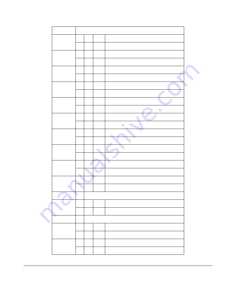
Bit 16
-
0
=
Gate Mode Disabled
-
1
=
Gate Mode Enabled
Bit 17
a
-
0
=
Normal Operation
-
1
=
High Pulse Energy
Bit 18
-
0
=
Hardware Emission Control Disabled
-
1
=
Hardware Emission Control Enabled
Bit 19
-
0
=
Normal Operation
-
1
=
Power Supply Failure
Bit 20
b
-
0
=
Front Panel Display is Unlocked
-
1
=
Front Panel Display is Locked
Bit 21
b
-
0
=
Keyswitch is in ON position
-
1
=
Keyswitch is in REM position
Bit 22
c
-
0
=
Waveform Pulse Mode OFF
-
1
=
Waveform Pulse Mode ON
Bit 23
a
-
0
=
Normal Operation
-
1
=
Duty Cycle Too High
Bit 24
-
0
=
Normal Operation
-
1
=
Low Temperature
Bit 25
-
0
=
Normal Operation
-
1
=
Power Supply Alarm
Bit 26
-
Reserved
Bit 27
-
0
=
Hardware Aiming Beam Control Disabled
-
1
=
Hardware Aiming Beam Control Enabled
Bit 28
-
Reserved
Bit 29
-
0
=
Normal Operation
-
1
=
Critical Error
Bit 30
-
0
=
Fiber Interlock OK
-
1
=
Fiber Interlock Active
Summary of Contents for QCW YLR-150
Page 4: ...ii Preface Audience...
Page 10: ...viii...
Page 30: ...1 20 Overview of the YLR Series Fiber Lasers Additional Safety Resources...
Page 43: ...2 13 Using Your Device Unpacking Instructions Figure 2 9 Unpacking a Unit from a Cardboard Box...
Page 45: ...2 15 Using Your Device Unpacking Instructions Figure 2 10 Unpacking a Unit from a Wooden Crate...
Page 57: ...2 27 Using Your Device Using the YLR Series Figure 2 13 24 Pin Connector Interfaces...
Page 64: ...2 34 Using Your Device Using the YLR Series Figure 2 16 Main Menu Screen...
Page 66: ...2 36 Using Your Device Using the YLR Series Figure 2 17 Sub Menus Screen...
Page 68: ...2 38 Using Your Device Using the YLR Series Figure 2 18 Sub Menus Screen...
Page 70: ...2 40 Using Your Device Using the YLR Series Figure 2 19 Sub Menus Screen...
Page 72: ...2 42 Using Your Device Using the YLR Series Figure 2 20 Sub Menus Screen...
Page 74: ...2 44 Using Your Device Using the YLR Series Figure 2 21 Sub Menus Screen...
Page 76: ...2 46 Using Your Device Using the YLR Series...
Page 138: ...4 48 Pulse Shaping Using the Pulse Shaper Program...
Page 153: ...A 9 Web User Utility Configuring a LAN Connection for Ethernet...
Page 154: ...A 10 Web User Utility Configuring a LAN Connection for Ethernet...
Page 164: ...C 8 Optical Fiber Connector Inspection and Cleaning Overview...
Page 187: ......


