2-4
Using Your Device
YLR Series — Front Panel View
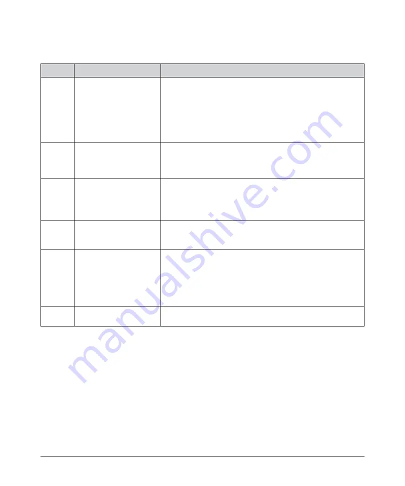
Table 2-3. Front Panel Descriptions
Figure 2-3 shows the front panel of the YLR-Series, which does not include a display.
Table 2-4 lists details for each component.
Item
Feature
Description
1
Keyswitch
(Local Interface option only)
The 3-position key switch controls the laser operation mode:
Left position — Chassis Powered On, Remote Control Mode
Central position — Chassis powered Off
Right position — Chassis Powered On, Local Control Mode
Note:
The key cannot be removed in the Remote Control Mode or
Local Control Mode positions.
2
Emergency Stop Button
(E-Stop)
(Local Interface option only)
Temporarily suspends power to the laser module. When active, the
main DC power supply is disabled. You can reset it by turning
clockwise.
3
Start Button with Indicator
(Local interface option only)
When pressed, turns On the internal main power supply of the laser
assuming that the Power key is in the Local Mode position.
When the indicator is On, the internal power supply is active and the
laser is capable of producing laser radiation.
4
Touch-Screen Display
(Local interface option only)
Use to set device settings and to display measured parameters and
alarm messages.
5
Emission On Indicator
Local Control Mode:
The indicator blinks for a short period after emission is enabled and
before laser radiation is emitted. once laser emission is ON, the
indicator is in the steady state “ON.”
Remote Control Mode:
The indicator is lit once emission is enabled.
6
Front Bezel Panel
Pull on each side to filter element for cleaning or replacement. Refer
to Table B-1 on page B-2 for more information.
Summary of Contents for QCW YLR-150
Page 4: ...ii Preface Audience...
Page 10: ...viii...
Page 30: ...1 20 Overview of the YLR Series Fiber Lasers Additional Safety Resources...
Page 43: ...2 13 Using Your Device Unpacking Instructions Figure 2 9 Unpacking a Unit from a Cardboard Box...
Page 45: ...2 15 Using Your Device Unpacking Instructions Figure 2 10 Unpacking a Unit from a Wooden Crate...
Page 57: ...2 27 Using Your Device Using the YLR Series Figure 2 13 24 Pin Connector Interfaces...
Page 64: ...2 34 Using Your Device Using the YLR Series Figure 2 16 Main Menu Screen...
Page 66: ...2 36 Using Your Device Using the YLR Series Figure 2 17 Sub Menus Screen...
Page 68: ...2 38 Using Your Device Using the YLR Series Figure 2 18 Sub Menus Screen...
Page 70: ...2 40 Using Your Device Using the YLR Series Figure 2 19 Sub Menus Screen...
Page 72: ...2 42 Using Your Device Using the YLR Series Figure 2 20 Sub Menus Screen...
Page 74: ...2 44 Using Your Device Using the YLR Series Figure 2 21 Sub Menus Screen...
Page 76: ...2 46 Using Your Device Using the YLR Series...
Page 138: ...4 48 Pulse Shaping Using the Pulse Shaper Program...
Page 153: ...A 9 Web User Utility Configuring a LAN Connection for Ethernet...
Page 154: ...A 10 Web User Utility Configuring a LAN Connection for Ethernet...
Page 164: ...C 8 Optical Fiber Connector Inspection and Cleaning Overview...
Page 187: ......


