2-23
Using Your Device
Using the YLR-Series
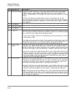
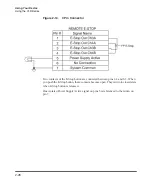
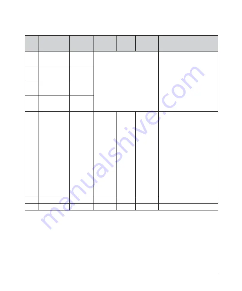
Table 2-8. 7-Pin Connector Pinouts
Pin
Signal Name
Signal
Type
Signal
Level
Signal
Drive
Typical
Response
Time
Description/Comments
1
E-Stop Out
Channel 3A
Contact
Closure to
pin 3
a
a.
Contact closure components rated 24VDC, 1A.
Direct connection to E-Stop
button on the front panel. If you
press Emergency Stop on the
front panel, channels 3 and 4 are
open.
Intended to be used by
integrators to shut down parts of
the system or entire system
when the laser front panel E-
stop is activated. Only
applicable to laser option with
display and controls on the front
panel.
2
E-Stop Out
Channel 4A
Contact
Closure to
pin 4
a
3
E-Stop Out
Channel 3B
Contact
Closure to
pin 1
a
4
E-Stop Out
Channel 4B
Contact
Closure to
pin 2
a
5
PS_Active1
Digital
Output
24 VDC
<100mA
(source)
120 ms
b
b.
Interlock response time (500 ms and 1.2s QCW models) must be additionally considered to
ensure the safe state of the device.
Note:
Connector housing is EMC rated and is the intended connection point for the shielding for the
customer’s cabling.
A high condition indicates that
the internal main power supply
is active.
Redundant signal for indicating
the power supply has been
activated. The signal is available
whether the laser is in Local
Control or Remote Control
Mode.
The integrator should use this
signal to warn operators using
the end product, that the power
supply is active and capable of
emitting laser radiation. It is the
responsibility of the purchaser/
end-user to bring the end
system into full compliance with
all applicable regulations.
6
No Connection
—
—
—
—
7
Common
Return
—
—
—
Return for signals on pins 5.
Summary of Contents for QCW YLR-150
Page 4: ...ii Preface Audience...
Page 10: ...viii...
Page 30: ...1 20 Overview of the YLR Series Fiber Lasers Additional Safety Resources...
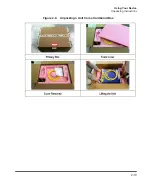
Page 43: ...2 13 Using Your Device Unpacking Instructions Figure 2 9 Unpacking a Unit from a Cardboard Box...
Page 45: ...2 15 Using Your Device Unpacking Instructions Figure 2 10 Unpacking a Unit from a Wooden Crate...
Page 57: ...2 27 Using Your Device Using the YLR Series Figure 2 13 24 Pin Connector Interfaces...
Page 64: ...2 34 Using Your Device Using the YLR Series Figure 2 16 Main Menu Screen...
Page 66: ...2 36 Using Your Device Using the YLR Series Figure 2 17 Sub Menus Screen...
Page 68: ...2 38 Using Your Device Using the YLR Series Figure 2 18 Sub Menus Screen...
Page 70: ...2 40 Using Your Device Using the YLR Series Figure 2 19 Sub Menus Screen...
Page 72: ...2 42 Using Your Device Using the YLR Series Figure 2 20 Sub Menus Screen...
Page 74: ...2 44 Using Your Device Using the YLR Series Figure 2 21 Sub Menus Screen...
Page 76: ...2 46 Using Your Device Using the YLR Series...
Page 138: ...4 48 Pulse Shaping Using the Pulse Shaper Program...
Page 153: ...A 9 Web User Utility Configuring a LAN Connection for Ethernet...
Page 154: ...A 10 Web User Utility Configuring a LAN Connection for Ethernet...
Page 164: ...C 8 Optical Fiber Connector Inspection and Cleaning Overview...
Page 187: ......


