CM-IW200
Instruction Manual
6
IMPORTANT: Do not install the iPort’s wall plate
in the same electrical box as AC house wiring,
a light switch, or any other high-voltage device
or control. The wall plate can share gang boxes
with other iPort Control Mount wall plates or
with controls such as A/B speaker switches,
infrared receivers, and volume controls, if
these other devices are rated as Class 2 devices
according to the National Electrical Code.
5. Use a stereo RCA audio cable to connect
the wall plate’s
audio
connectors to a
source input on the local-zone audio
system, as shown in Figure 3.
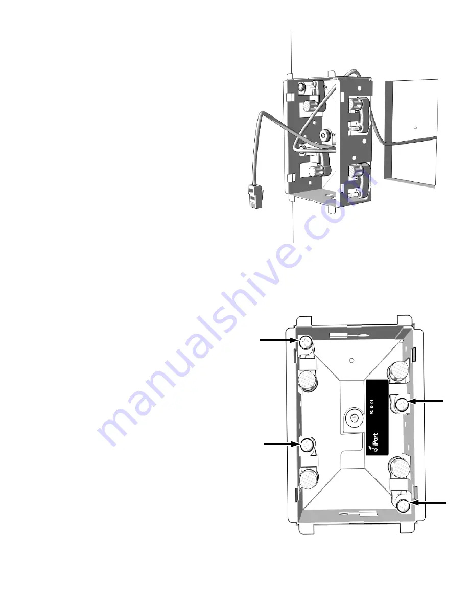
6.
Prior to placing the mounting cradle into
the wall, pull a sufficient length of the Cat5
cable and its attached RJ-45 connector
through the opening in the top of the
mounting cradle, as shown in figure 4.
7.
The retainer and cradle are pre-assembled
with internal packaging materials.
Disassemble by removing the four screws.
Discard the foam block and card insert.
8.
Insert the Control Mount mounting cradle
into the opening in the wall.
Note: The Roto-Lock system can accom-
modate wall thickness of 3/8” to 3/4”
and can be extended to 1 1/4” with the
removal of the toggle caps.
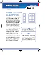
9. Hand-tighten the four Roto-Lock screws on
the Control Mount’s utility box as shown
in Figure 5. The Roto-Lock clamps will
automatically rotate into position behind
the wall and begin clamping the mount.
• When you notice resistance on the four
screws, the Control Mount has been
clamped successfully.
CM
-IW
20
0
®
U.S. Patent No. 7,493,142 Additional Patents Pending
Designed and Enginee
red in the USA
33-5522 1-11
LA
BE
L S
IZ
E: 2
” x 0
.5
”
Figure 5: Roto-Lock Screw Locations
Figure 4: Mounting Cradle Installation


