8
iPor t ver. FS
Ins tr uction Manual
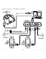
iPort System Connections — FS-1 / FS-2
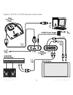
See
Figure 5
The iPort FS-1 and FS-2 systems’ unbalanced audio and video outputs are designed for use in a local-
zone system where the audio/video equipment is located less than 25 feet from the iPort Basic
Connection Box.
In FS-1 systems the iPod is controlled only from its front panel; in FS-2 systems the iPod can be
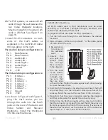
controlled from its front panel, from the Multi-Function Buttons on the iPort Dock (see above), or from
an optional iPort Standard or EX remote control (or a compatible 3rd-party remote).
1. The iPort Dock must be located within 2 meters of the Basic Connection Box and within 2 meters of
the computer. The Connection Box should be located near a source of AC power.
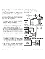
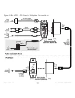
2. Connect the iPort system to the audio and video components as shown in
Figure 5
:
• Connect the supplied Double Cable to the iPort Dock, the Basic Connection Box and the com-
puter’s USB port.
• Use a stereo RCA audio cable to connect the Connection Box to a source input on the local-zone
audio system.
• Use a composite video and/or S-Video cable to connect the Connection Box to an input on the
video equipment.
Note: You can use both the S-Video and composite video connections simultaneously.
• If you’re using a powered speaker system (computer speakers) as a local zone audio system,
connect the Line Out jack into the powered speaker system’s input.
Note: Do not plug stereo headphones into the Line Out jack.
• Plug the included 15V DC power supply into the
Power
connector on the Connection Box.
3. After confirming that all of the connections have been made correctly, plug the power supply into
a wall outlet.


