


iPOWER TPD-800A User Manual
15
leading-in MIB file on the SNMP management platform, user can monitor and manage the device status
information and alarm Trap information after translating and editing success, the details information of device
status are as detailed in figure 2-1, figure 2-2,
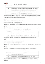
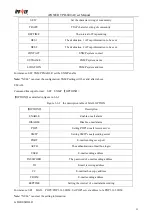
1). The status of the device and sensor can be read through the table format of SNMP software, details as below:
Figure 2-1 the information table of device output status
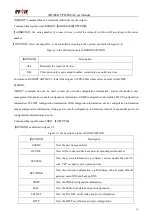
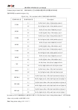
Figure 2-2 the information table of device sensor status
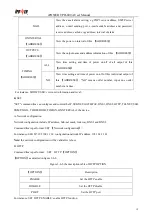
Menu
Description of menu
Device name
Display the connected device name
Device Type
Display the connected device model
Series No
Display the current hardware device series number
ON Interval
The interval of power on
Total Load Value
Display the total output load current
Temperature 1
Display the current connection status and temperature of temperature sensor 1
Humidity 1
Display the current connection status and humidity of humidity sensor 1
Temperature 2
Display the current connection status and temperature of temperature sensor 2
Humidity 2
Display the current connection status and humidity of humidity sensor 2
Temperature 3
Display the current connection status and temperature of temperature sensor 3
Humidity 3
Display the current connection status and humidity of humidity sensor 3
Door 1
Display the current status of door sensor 1
Door 2
Display the current status of door sensor 2
Smoke
Display the current status of smoke sensor
Water Logging
Display the current status of waterlogging sensor
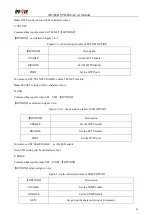
Menu
Description of menu
XX output ID
XX stands for device name, output ID display the device ID address
Name
The output end name
Status
The corresponding switch on/off status of each output
Load Value
The corresponding current of each output
Load Low limit
The corresponding minimum value of each output
Load High limit
The corresponding maximum value of each output


