16
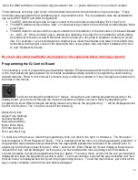
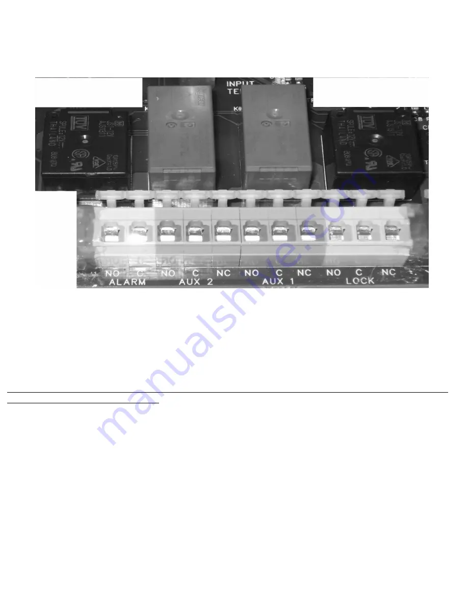
The IQ Control Board is equipped with (2) 10 amp programmable relays. These relays can be configured to
perform a variety of functions. The output terminals for these relays are directly below their corresponding
relay.
The output relay functions and input terminal options can be programmed in the Auxiliary Settings Menu.
The new revision of the IQ Motor board has two (2) new on board push buttons labeled “OPEN” and “CLOSE”. These
buttons will be implemented in a later software revision to be used as a motor limit learning protocol. However, they may
be currently used to operate the gate manually for the means of setting the positive limits and overall travel of the gate. To
utilize the manual override buttons, perform the following:
1.
Unplug the RJ45 Ethernet cable from the DISPLAY/PROGRAMMING BOARD
2.
Push and hold the desired manual override button on the MOTOR BOARD
Please note that the manual override button will ignore and run past the limit switches. The gate will not stop unless the
button is released or the power is shutoff.
Wiring the IQ Control Board
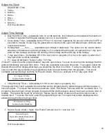
The IQ Control board utilizes spring loaded terminal connections. To connect or disconnect wires, push the
white prong inwards towards the circuit board using a 3/16
th
inch blade screwdriver; insert or remove the
desired wire, and release the pressure on the terminal spade.
The IQ control board has numerous terminals to accommodate your entire accessory wiring needs. The IQ
control board uses pull down contacts so that the ground or “GND” terminals should be used as the common
contact to complete the circuit for your normally open contacts. The IQ control board also consists of 2
separate power output supplying areas. The Red terminals located at the far most bottom right corner of the
Terminal board are labeled {+ 12V}. These 4 terminals can be used for your 12 vdc positive power output
terminals and are only designed for 12vdc accessory power. Maximum output is 500ma.
The 5 Orange terminals that are located directly above these are labeled: {28/14 VDC}. These 5 terminals are
whatever voltage that the operator is being supplied with, rather it be 12 vdc or 24 vdc.


