background image

GW-USB-13A

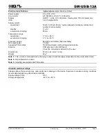
Electrical specifications                       

(

typical values

 unless otherwise stated)

Power supply  

            5.0 ± 0.35 V DC

Accumulator                                                     LIP-552240 (Li-Pol 3.7 V, 400 mAh)
Display                                                                OLED 1“, white, 128 x 64 pixels. Viewing area 120 x 64 pixels only.
USB

V2.0 Compliant SIE

Supply current  
    operational

18 mA to 35 mA, 25 mA 

1

 typical (depends on display contrast and 

number of active pixels)

    standby

11 µA 

2

accumulator charging

                    85 mA

Temperature range
    operational

            0 °C to +60 °C

    accumulator charging

0 °C to +45 °C

Frequency range

868 MHz or 916 MHz (SW selectable)

RF output power                                              1.3 mW
Supported TR modules 

                        TR-52B and higher, without integrated antenna

Antenna

PCB antenna on the GW board
It must be connected (soldered) by the user

Dimensions

93 mm x 42 mm x 14 mm

Weight 

            42 g 

3

Note 1: 

 This current is increased due to charging in case of external supply (depended on the accumulator state).

Note 2: 

 All peripherals shut down.

Note 3: 

 Including accumulator and TR module.

Absolute maximum ratings

Stresses above those values may cause permanent damage to the device. Exposure to maximum rating conditions
for extended periods may affect device reliability.
Supply voltage (VCC)

5.5 V

Storage temperature 

-40 °C to +85 °C

© 2014  MICRORISC s.r.o.

www.iqrf.org

User_Guide_GW-USB-13A_140331

Page 3

Summary of Contents for GW-USB-13A

Page 1: ...GW USB 13A IQRF USB Gateway with OLED User s Guide 2014 MICRORISC s r o www iqrf org User_Guide_GW USB 13A_140331 Page 1 ...

Page 2: ...ion GW USB 13A is a generic equipment i e the hardware is fixed and the user can implement specific functionality by software only Applications should be developed using the DS PAGER development set Applications Home automation Portable controllers and pagers Diagnostic tool Portable service tool for IQRF network management Key features OLED display 1 128 x 64 pixels white 8b microcontroller USB v...

Page 3: ...ctable RF output power 1 3 mW Supported TR modules TR 52B and higher without integrated antenna Antenna PCB antenna on the GW board It must be connected soldered by the user Dimensions 93 mm x 42 mm x 14 mm Weight 42 g 3 Note 1 This current is increased due to charging in case of external supply depended on the accumulator state Note 2 All peripherals shut down Note 3 Including accumulator and TR ...

Page 4: ...f all three pushbuttons is fully under software control Beeper The functionality is fully under software control TR module The transceiver module is inserted in SIM card connector User program should be uploaded by an external programmer outside the GW or inside the GW using RFPGM wireless upload RF PGM should be enabled in external programmer first see the IQRF IDE help Antenna PCB antenna built ...

Page 5: ...16 MHz SW selectable Recommended options DS PAGER Development set for GW USB 13A TY A6A Wall adapter for charging from mains Document history 140331 TR 52D inside 120313 Upgraded to GW USB 13A with OLED 128 x 64 100726 Revised TR 52B inside Related development set renamed to DS PAGER 090825 Related development set renamed to DK GW USB 13 xxx 090626 Just visual aspects improved 090514 GW USB 13 fir...

Page 6: ...ein are property of their respective owners Legal All information contained in this publication is intended through suggestion only and may be superseded by updates without prior notice No representation or warranty is given and no liability is assumed by MICRORISC s r o with respect to the accuracy or use of such information Without written permission it is not allowed to copy or reproduce this i...

Reviews: