©2016 IQtronic technologies Europe, s.r.o.
Page 5 of 22
2
Installation
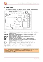
2.1 Description of the device board, inputs and outputs
DEF
This button is for ouputs control – a short press. Or for the factory
default settings.
10M Eth
Ethernet RJ-45 jack. Passive PoE support (incompatible with
802.3af, 6-36VDC ± 20%).
6-24VDC
Power connector, recommended voltage is 12VDC ± 20%.
O1,O2
Yellow LED – outputs status.
PWR
Red LED, blinks at intervals of 1 sec – regular operation.
ETH
Green LED, sby shining indicates connection to Ethernet. By
dimming indicates its activity.
GND
0VDC potential for sensors (yellow wire, yellow pin pin)
T1,T2
Sensor input for temperature sensor (white wire, green pin)
VDD
Power supply for sensors (green wire, green pin pin)
NC,C1,NO
Output 1 - relay contacts - switchable, 1A/30VDC max.
NC,C2,NO
Output 2 - relay contacts - switchable, 1A/30VDC max.
Note:
Improper wiring and short-circuits on board connections may lead to
permanent damage of the product, which is not covered by the
manufacturer's warranty


