background image

21

PORSCHE 911 GT3 R  |  USER MANUAL

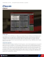
SPRING SELECTED/SPRING RATE

This setting determines the installed corner spring stiffness. Stiffer springs will result in a smaller variance in ride height between 
high and low load cases and will produce superior aerodynamic performance through improved platform control; however, they 
will also result in increased tire load variation which will manifest as a loss in mechanical grip. Typically the drawbacks of stiffer 
springs will become more pronounced on rougher tracks and softer springs in these situations will result in increased overall 
performance. Corner spring changes will influence both roll and pitch control of the platform and ARB changes should be 
considered when altering corner spring stiffnesses in order to retain the same front to rear roll stiffness and overall balance. 
When reducing corner spring stiffness the ARB stiffness (either via blade or diameter depending on the size of the corner spring 
change) should be increased to retain the same roll stiffness as previously. 11 options for spring rate are available ranging from 
200 N/mm (1371 lbs/in) to 400 N/mm (2286 lbs/in) in 20 N/mm (114 lbs/in) steps. Spring perch offsets must be adjusted 
to return the car to the prior static ride heights after any spring rate change.

LS COMP DAMPING

Low speed compression affects how resistant the shock is to compresion (reduction in length) when the shock is moving at 
relatively low speeds, usually in chassis movements as a result of driver input (steering, braking, & throttle) and cornering 
forces. In this case -24 is minimum damping (least resistance to compression) while 0 is maximum damping (most resistance to 
compression). Increasing the low speed compression damping will result in a faster transfer of weight to this corner of the car 
during transient movements such as braking and direction change with increased damping usually providing an increase in turn-in 
response but a reduction in overall grip in the context of front dampers.

HS COMP DAMPING

High speed compression affects the shock’s behavior in high speed travel, usually attributed to curb strikes and bumps in the 
track’s surface. Higher compression values will cause the suspension to be stiffer in these situations, while lower values will allow 
the suspension to absorb these bumps better but may hurt the aerodynamic platform around the track. At smoother tracks more 
high speed compression damping will typically increase performance while at rougher tracks or ones with aggressive kerbs less 
high speed compression damping can result in an increase in mechanical grip at the expense of platform control. 0 is maximum 
damping while -24 is minimum damping.

LS RBD DAMPING

Low speed rebound damping controls the stiffness of the shock while extending at lower speeds, typically during body movement 
as a result of driver inputs. Higher rebound values will resist expansion of the shock, lower values will allow the shock to extend 
faster. Higher rebound values can better control aerodynamic attitude but can result in the wheel being unloaded when the 
suspension can’t expand enough to maintain proper contact with the track. When tuning for handling, higher front low speed 
rebound can increase on-throttle mechanical understeer (but reduce nose lift) while lower values will maintain front end grip 
longer, helping to reduce understeer, but will allow more splitter lift. Excessive front rebound can lead to unwanted oscillations due 
to the wheel bouncing off of the track surface instead of staying in contact. 0 is maximum damping (most resistant to extension) 
while -24 is minimum damping (least resistance to extension).

HS RBD DAMPING :

High-speed rebound adjusts the shock in extension over bumps and curb strikes. Higher values will reduce how quickly the shock 
will expand, while lower values will allow the shock to extend more easily. Despite not having as much of an effect on handling 
in result to driver inputs, High-speed rebound can produce similar results in terms of aerodynamic control and uncontrolled 
oscillations if set improperly. 0 is maximum damping while -24 is minimum damping.

PORSCHE 911 GT3 R  |  ADVANCED SETUP OPTIONS  |  CHASSIS

Summary of Contents for Porsche 911 GT3 R

Page 1: ...1 PORSCHE 911 GT3 R USER MANUAL...

Page 2: ...iRacing Setup 6 Quali 11 Race 1 7 Lockup Light Clusters 12 Tire Settings 14 Pit Limiter Shift Lights 13 Chassis 17 Traction Control Activation 12 Aerodynamics 15 Tires Aero 14 Front End 17 In Car Dia...

Page 3: ...R is both a beloved and successful piece of kit Immediately successful out of the gate thanks to a win in its first attempt at the Bathurst 12 Hour you can find the 911 GT3 R running at the front of...

Page 4: ...ENSION WATER COOLED REAR MOUNTED FLAT 6 BOXER L E N G T H 4629mm 182 2in D I S P L A C E M E N T 4 0 Liters 244 14CID T O R Q U E 280lb ft 380Nm W I D T H 2002mm 78 8in R P M L I M I T 9450RPM P O W E...

Page 5: ...rends over a number of laps Once you are confident that you are nearing your driving potential with the included baseline setups read on to begin tuning the car to your handling preferences GETTING ST...

Page 6: ...ion For example a setup for Talladega will pass at Daytona but likely will not pass at Bristol If you would like to customize the setup simply make the changes in the garage that you would like to upd...

Page 7: ...l used this stint fuel consumption per lap fuel pressure and current fuel level Qual forgoes most of these detailed parameters and instead displays only lap time predicted lap time and total fuel rema...

Page 8: ...ntly selected engine map TH S Currently selected throttle map S12 3 ensor backup function position non adjustable G12 6 Gearbox backup function position non adjustable ROW 3 CENTER TYRE PRESS Tire Pre...

Page 9: ...ent session lap AC 0 Currently selected A C map non adjustable ROW 2 LEFT FUEL USED Fuel used Litres or US gallons FUEL PER LAP Fuel used per lap Litres or US gallons FUEL PRESS Fuel pressure Bar or p...

Page 10: ...kup function position non adjustable G12 6 Gearbox backup function position non adjustable ROW 3 CENTER TYRE PRESS Tire Pressures left front right front left rear right rear ROW 4 MIL Malfunction indi...

Page 11: ...urrently selected A C map non adjustable ROW 2 LEFT LAP TIME Current session lap FUEL LEVEL Fuel remaining in the tank Litres or US gallons ROW 2 CENTER LARGE NUMBER Currently selected gear ROW 2 RIGH...

Page 12: ...the road wheel that s locking e g left side lights in purple indicate a front left lockup The number of lights indicates the severity of the lockup with one light being a minor lockup and four being...

Page 13: ...rrent road speed will display across the top of the dashboard while the left and right lockup light clusters will also illuminate completely in green Should you be above the pit speed limit the green...

Page 14: ...s Cold pressures should be set to track characteristics for optimum performance Generally speaking it is advisable to start at lower pressures and work your way upwards as required ADVANCED SETUP OPTI...

Page 15: ...while on track These values are measured in three zones across the tread of the tire Inside Middle and Outer TREAD REMAINING The amount of tread remaining on the tire once the car has returned to the...

Page 16: ...e total cornering grip capability in medium to high speed corners but will also result in a reduction of straight line speed Rear wing angle should be adjusted in conjunction with front and rear ride...

Page 17: ...e stiffness of the front suspension in roll such as when navigating a corner Increasing the ARB size will increase the roll stiffness of the front suspension resulting in less body roll but increasing...

Page 18: ...rear brake calipers A larger master cylinder will reduce the line pressure to the rear brakes this will shift the brake bias forwards and increase the pedal effort required to lock the rear wheels A s...

Page 19: ...sensitivity position 1 through to highest intervention sensitivity position 11 Position 0 disables the traction control completely Position 5 is the recommended baseline setting More intervention wil...

Page 20: ...are made via the spring perch offset adjustments at each corner FRONT RIDE HEIGHT Distance from ground to a reference point on the chassis Since these values are measured to a specific reference point...

Page 21: ...t dampers HS COMP DAMPING High speed compression affects the shock s behavior in high speed travel usually attributed to curb strikes and bumps in the track s surface Higher compression values will ca...

Page 22: ...arger proportion of the felt steering weight relative to the tires pneumatic trail This will result in a heavier overall steering feel but a possible loss in felt feedback from the tire Increasing cas...

Page 23: ...ncreasing the cars tendency to understeer on throttle application HS COMP DAMPING High speed compression affects the shock s behavior in high speed travel usually attributed to curb strikes and bumps...

Page 24: ...This means that individual values on the rear wheels are twice as powerful as the combined adjustment at the front of the car when the rear toes are summed together Generally it is advised to keep th...

Page 25: ...available 35 mm softest and 45 mm stiffest DIFF PRELOAD Diff preload is a static amount of locking force present within the differential and remains constant during both acceleration and deceleration...

Reviews: