2–16
Section 2 — INSTALLATION
CIBLE
CONE DE
VISEE
TROU DE
VISEE
MODLINE 4
HUBLOT
90
°
e
e
MAX = 45
°
CIBLE
2.1
2
SPECIAL MOUNTING SITUATIONS
Sometimes it is necessary to view a target through
a sight hole, or through an aperture sealed by a
window. There are also times when the physical
restraints of the process environment make it diffi-
cult, if not impossible, to mount the MODLINE 4 for
a convenient, head-on view of the target. These
and other 'special situations" call for special
mounting procedures.
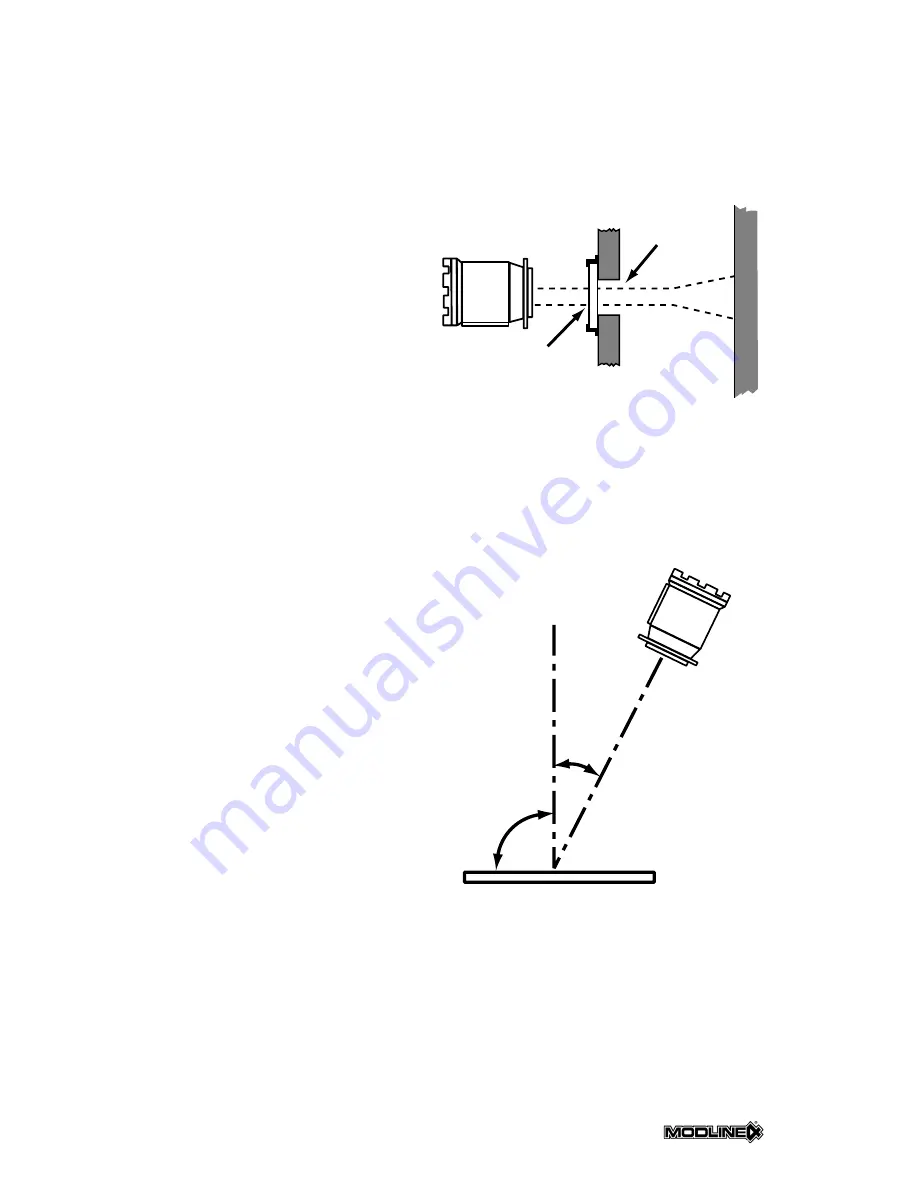
Fig. 2.17 is an example of a MODLINE 4 sighted
on a target through a sight hole cut for the pur-
pose. A sight window is shown mounted on the
sight hole.
Two special considerations immediately present
themselves in this situation:
1. The sight hole diameter must be large enough
to allow the instrument to view the target. Never
obstruct any part of the Cone of Vision.
2. The window must be able to transmit the
infrared energy. Consult Table 3.1 of Section 3
to determine the proper material for your MOD-
LINE 4. If a window is used, it must be kept
clean or low temperature indications will result.
Acute viewing angles can present problems of
reduced emissivity values, particularly if you are
dealing with smooth target surfaces.
Figure 2.18 shows the permissible angles when
viewing smooth surfaced objects such as metals,
glass or plastics. Angles of up to 45° from the per-
pendicular will not appreciably affect the measure-
ment. Angles greater than 45° should be avoided.
An increase in reflectance occurs when smooth
surfaces are viewed at large angles, and conse-
quently the target emissivity decreases.
These are just a couple of special situations and
the things to watch for in dealing with them. If you
run into these or other situations that may cause
problems, consult IRCON Applications
Engineering. Our many years of experience in fac-
ing and solving temperature measurement prob-
lems can be of great benefit!
NOTE: Section 6 offers some application guides
that may be helpful.
FIG. 2.17 – VIEWING TARGET THROUGH
SIGHT HOLE AND WINDOW
FIG. 2.18 – VIEWING ANGLE LIMITATIONS
FOR SMOOTH TARGET SURFACES
SIGHT
HOLE
WINDOW
TARGET
TARGET
MODLINE 4
CONE OF
VISION
Summary of Contents for Modline 4
Page 3: ......
Page 5: ......
Page 6: ......
Page 34: ......
Page 35: ......
Page 36: ...Section 2 INSTALLATION 2 21 ...
Page 37: ...Section 2 INSTALLATION 2 22 ...
Page 49: ...Section 4 MAINTENANCE SERVICE 4 4 NOTES ...


