2–18
Section 2 — INSTALLATION
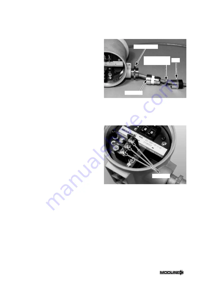
FIG. 2.20 – CONNECT THE SERIES LOOP WIRES
T
O THE MODLINE 4 TERMINAL STRIP: plus (+) and
minus (-), and EARTH GROUND TERMINAL SCREWS.
CONNECT
FIG. 2.19 – CORD GRIP WITH CABLING
GROMMET
CAP
COMPRESSION
SPRING
CONDUIT HUB
CABLE ROUTING FOR THE INSTRUMENT
Remove the back cover of the enclosure. Unscrew
by hand, or if the cover is sealed tightly, use a rod
or bar in the torquing slots (standard enclosure) or
against the torquing studs (water-cooled enclo-
sure).
Thread the cables through the cord grip grommet
into the MODLINE 4 case. Figure 2.19 illustrates
proper assembly of the cord grip, grommet, and
cable. When assembling the parts of the cord grip,
you will thread components onto the cabling in
their specified order, which is as follows:
1.
Hub cap and grommet
2.
Compression spring
3.
Connection housing
4.
Conduit hub
Insert Wires
Prepare the series loop cable by stripping the two
wires. Leave enough of the braided shield exposed
so that the compression spring can make ade-
quate contact. Attach the signal cable shield to
earth ground at the power supply end. Insert the
wires under the compression clamps on the termi-
nal strip as shown in Fig. 2.20.
NOTE: For proper termination of your system
(including systems with multiple device loads),
refer to Section 2.15.
If you ordered your MODLINE 4 with a peak picker
option, refer to Section 2.16.
Summary of Contents for Modline 4
Page 3: ......
Page 5: ......
Page 6: ......
Page 34: ......
Page 35: ......
Page 36: ...Section 2 INSTALLATION 2 21 ...
Page 37: ...Section 2 INSTALLATION 2 22 ...
Page 49: ...Section 4 MAINTENANCE SERVICE 4 4 NOTES ...


