2–2
3
Section 2 — INSTALLATION
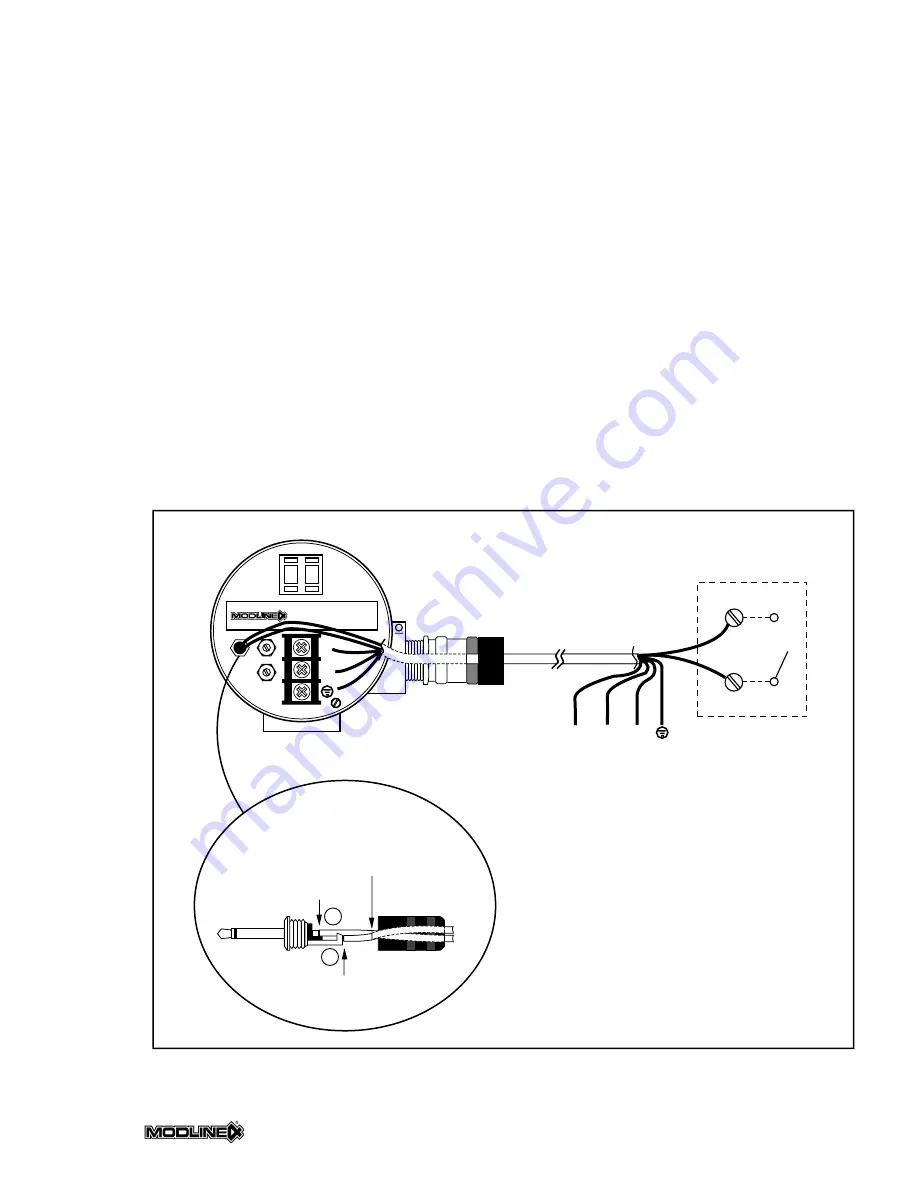
FIG. 2.2
3
– PEAK PICKER CABLE AND SWITCH WRING
+
–
EXTERNAL
SPST SWITCH
MODLINE 4
BACK PANEL
®
MOD.
S.N. SP.
+
+
–
–
9
9
ε
;
;
;
;
CRIMP
AND
SOLDER
SOLDER
PLUG COVER
CUT SHIELD HERE;
DO NOT TERMINATE
PEAK PICKER
PLUG WIRING DETAIL
1
2
;
+
–
1
2
SHIELD
2.1
5
PEAK PICKER WIRING
If you ordered the peak picker option and you are
planning to reset the peaked signal remotely, you
will need to wire to the peak picker plug and a
remote switch as it is shown in Fig. 2.25.
Customer-Supplied Items
Customer-supplied items needed to install the
peak picker are listed below.
• Wire: 5-conductor cable with overall shield (con-
ductor should be at 18–22-gauge)
• Switch (for remote reset): SPST
• Wire clipper and soldering iron
To Install
To wire the peak picker plug and remote switch,
follow these steps:
1. Strip the two peak picker remote reset wires.
2. Thread the two wires through the plug cover.
3. Solder Wire 1 (see Fig. 2.25) to the center sol-
der cup of the plug.
4. Solder Wire 2 (see Fig. 2.25) to the solder/
crimp lug and crimp.
5. Screw down the plug cover over wires.
6. Connect the cable shield to an external Earth
Ground at the switch end.
Summary of Contents for Modline 4
Page 3: ......
Page 5: ......
Page 6: ......
Page 34: ......
Page 35: ......
Page 36: ...Section 2 INSTALLATION 2 21 ...
Page 37: ...Section 2 INSTALLATION 2 22 ...
Page 49: ...Section 4 MAINTENANCE SERVICE 4 4 NOTES ...


