www.irf.com
Page 29 of 50
IRAUDAMP5 REV 3.1
0
100
200
400
500
600
10%
20%
30%
40%
50%
60%
70%
80%
90%
Duty Cycle
O
p
er
at
in
g Fr
u
e
n
cy (
k
H
z
)
300
eq
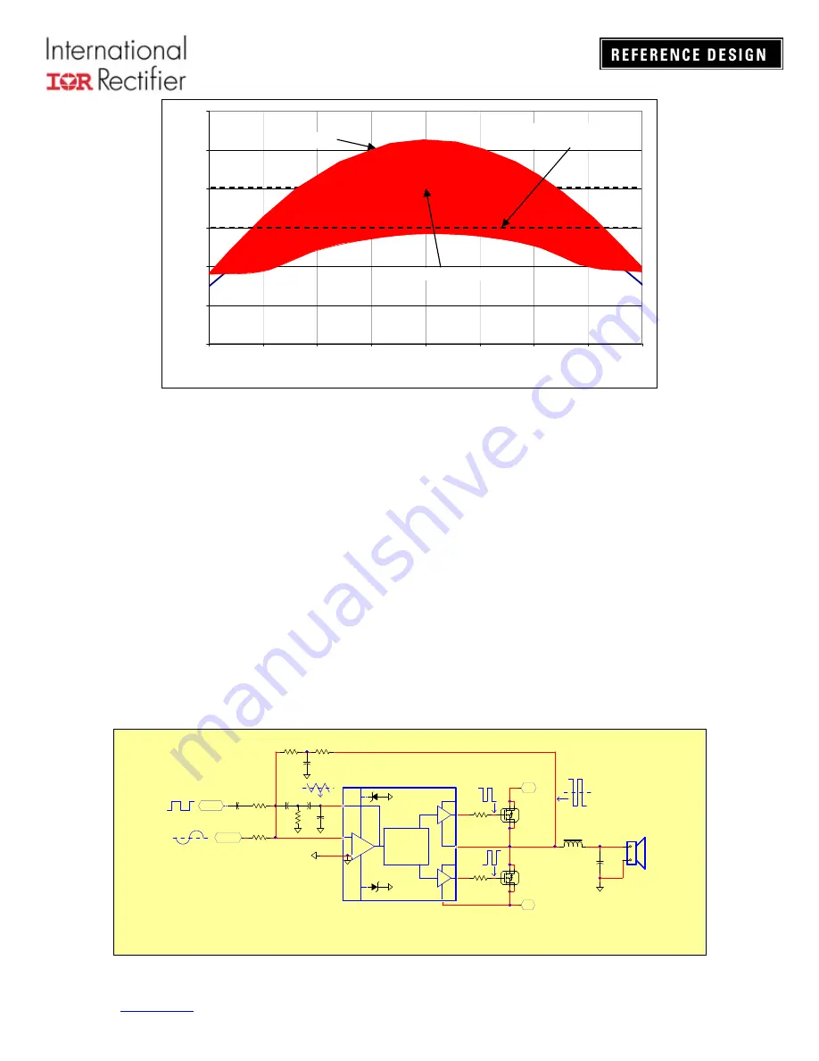
Typical Lock Frequency Range vs. PWM Duty Ratio
(Self-oscillating frequency set to 400 kHz with no input)
Fig 32
The output power range, for which frequency-locking is successful, depends on what the locking
frequency is with respect to the self-oscillating frequency. As illustrated in Figure 33, the locking
frequency is lowered (from 450kHz to 400kHz to 350kHz and then 300kHz) as the output power
range (where locking is achieved) is extended. Once locking is lost, however, the audio
performance degrades, but the increase in THD seems independent from the clock frequency.
Therefore, a 300 kHz clock frequency is recommended, as shown on Fig 34
It is possible to improve the THD performance by increasing the corner frequency of the high
pass filter (HPF) (R17 and C15 for Ch1 Fig 33) that is used to inject the clock signal, as shown in
Figure 33 below.
This drop in THD, however, comes at the cost of reducing the locking range. Resistor values of
up to 100 kOhms and capacitor values down to 10pF may be used.
+
-
.
.
0V
SYNC
R13
IN-
COMP
.
+VAA
IRS2092S
LO
VS
VCC
VB
-B
+B
LP Filter
0V
22k
R22
HO
INPUT
CH1
Integrator
Modulator
and
Shift level
COM
GND
33pF
C15
IRF6645
Q4
IRF6645
Q3
Switching Frequency Lock / Synchronization Feature
Fig 33
Self-oscillating frequency
Locking range
Self-oscillating frequency
Suggested clock frequency
for maximum locking range
Summary of Contents for IRAUDAMP5
Page 45: ...www irf com Pa Figure 39 PCB Layout Motherboard ge 44 of 50 IRAUDAMP5 REV 3 1 Top Layer ...
Page 46: ...www irf com Top silk screen Page 45 of 50 IRAUDAMP5 REV 3 1 ...
Page 47: ...www irf com Page 46 of 50 IRAUDAMP5 REV 3 1 Bottom ...
Page 48: ...www irf com Page 47 of 50 IRAUDAMP5 REV 3 1 4 0 ...
Page 49: ...www irf com Page 48 of 50 IRAUDAMP5 REV 3 1 Bottom Silkscreen 4 0 ...


