background image

Inf

o

rm

at

io

an

d

  Non

-c

o

nt

rac

tua

l v

isu

al

s. 

Sub

je

ct

 t

o

 t

ec

hn

ic

al

 c

ha

ng

e wi

tho

ut

 no

ti

ce

This document is the property of IRFTS. It shall not be reproduced or shared with third party without agreement IRFTS 

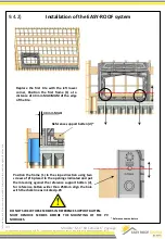
9.5.1) 

Grounding


If  the  grounding  is  not  done  by  connecting  the  cable  directly  to  the  PV  module,  perform  the  following 
operations. 
 
1) Identify the middle brackets grounded during assembly. (See p. 36) 

(View with local section) 

Glaw on the PV module 


Option 1)  
Connect the ground by connecting the middle brackets with the cable lugs and connect 
the ground to the PV module.  

2) Then ensure that the connection is made between the PV module and the middle bracket (6) and that 
this connection is less than 2 Ohms.  

Option 2)  
Place the  claw on the back of the PV module so that it is sits on the grounded bracket. 

47 

Model "M-1" 60 Cells 6" Landscape 

Connect the ground wire to 
the frame of the module, see 
manufacturer instruction.


Summary of Contents for EASY ROOF M-1 EVOLUTION

Page 1: ...ial Public building Agricultural and Industrial roofs INS INO2 14 O255 Version 1 3 29 07 14 Document validated by NEW TECHNICAL SURVEY No L14CC0075 The EASY ROOF system is insured provided that the modules have approvals IEC 61215 and IEC 61730 INSTALLATION INSTRUCTIONS EASY ROOF Model M 1 EVOLUTION For module 60 cells 6 LANDSCAPE See the module on compatibility at www irfts com Applicable to inst...

Page 2: ...as 18 9 Easy Roof system assembly instructions 20 9 1 PV array centered on rake 9 1 1 Removal of tiles 20 9 1 2 Definition of bottom flashing support batten 20 9 1 3 Positioning the reference support batten 21 Installation of bottom flashing support batten 21 9 1 4 Installation of the bottom flashing 22 9 2 PV array placed at the gutter eave 9 2 1 Removal of tiles 23 9 2 2 Position of the flooing ...

Page 3: ...duced or shared with third party without agreement IRFTS Table of Contents 3 Model M 1 60 6 Cells Landscape Annex 1 Pyramid assembly 49 à 55 Annex 2 Lateral Edge metal sheet definition 56 Annex 3 Tile s alignment over the Top Flashing 57 à 58 Annex 4 Connection of electric cables and grounding 59 à 62 Annex 5 Installation on long slope 63 à 67 ...

Page 4: ...volution 6 P004MV40 5 Simple fixing clamp Evolution A001V40 6 Double fixing clamp Evolution 1 A002V40 7 Double large fixing clamp Evolution 1 A009V40 8 Double Bracket Evolution A004V40 9 Single bracket Evolution A003V40 10 Stainless steel rounded end screw 6x40 A2 V003V02 11 clamp screw M6 x 40 stainless steel A2 module from 40 to 50 2 V013V02 12 clamp screw M6 x 30 stainless steel A2 module from ...

Page 5: ...ge without notice This document is the property of IRFTS It shall not be reproduced or shared with third party without agreement IRFTS Representation of parts 2 3 6 7 8 9 5 13 14 15 18 17 16 1 3 5 Model M 1 60 6 Cells Landscape 1 Top flashing included in the frame 4 ...

Page 6: ...frame P002MV40 Left flashing P003MV40 Right flashing P004MV40 Top deflector Codification can change according to the choice of the material Roofing felt Roofing underlay We impose the installation of a roofing felt roofing underlay before the installation of the system of integration EASY ROOF This roofing felt roofing underlay must comply with local regulation 1 lateral flashing by frame height 1...

Page 7: ...hout agreement IRFTS Use different flashings depending on the configuration of the PV field Multiple combination for clearing the roof window or chimney PANEL PANEL PANEL PANEL A G A G A G A G PANEL A D PANEL PANEL PANEL PANEL PANEL PANEL PANEL PANEL PANEL PANEL A D PANEL A D A D PANEL Chim ney A G A G A D A D Roof window PANEL X column Line 1 4 7 Model M 1 60 6 Cells Landscape ...

Page 8: ...roperty of IRFTS It shall not be reproduced or shared with third party without agreement IRFTS Model M 1 60 6 Cells Landscape 8 4 1 Possible shift of panels vertically Shift with constant step Variable shift X 1 step Support batten End clamp and bracket Middle clamp and bracket Frame End clamp and bracket ...

Page 9: ... high frieze support which is indimension the frame 3 For an installaiton with 6 bracket per module remove the plug in the center of the frame 4 For all frames except those placed on top of the PV field remove the plug for the middle bracket passage 1 3 2 PV module width 985 986 PV module width 994 995 module width 1001 Pre mount a centering wedge in the slides of each middle clamp 6 Select the mo...

Page 10: ...onnect the ground wire to one middle bracket 8 for two PV modules b1 The connection between the PV module and the mounting bracket connected to the earth is done using the middle clamp See Installation on page 47 of this document Middle clamp b2 It is possible to make the link between the PV module and the middle bracket 8 connected to ground using a claw See manufacturer documentation Preparation...

Page 11: ... 55 Nbx Number of columns of PV module Field width mm Dimension of the photovoltaic field dimension X 1 2 3 4 5 6 7 8 9 10 11 12 13 14 15 16 X MINI size 1811 3512 5213 6914 8615 10316 12017 13718 15419 17120 18821 20522 22223 23924 25625 27326 Number of modules in width with assembly to lateral edges E g 1701 x 12 2 x 55 20522 a Common installation with tiles on both side b Edge installation no ti...

Page 12: ...A a a Determination of dimension A Bottom flashing batten The C dimension is the Minimum batten width necessary to avoid reverse slope on the bottom flashing It s possible to use a wider batten this will simply raise up the PV field Example Dimension of the photovoltaïc field PV field centered on rake direction Gutter eave installation Step Step of the system in rake direction see table below Nby ...

Page 13: ...m Dimension of the photovoltaïc field 1 2 3 4 5 6 7 8 9 10 11 12 13 14 15 16 L MINI size 1811 3512 5213 6914 8615 10316 12017 13718 15419 17120 18821 20522 22223 23924 25625 27326 Number of modules in width with assembly of lateral edges E g 1701 x 12 2 x 55 20522 a Common installation with tiles on both side b Edge installation no tiles on each side 1 Calculate the width of system dimensions to b...

Page 14: ...ly raise up the PV field 2 Calculation of the overall height of the installed system b Determination of dimension H Dimensions of Easy Roof system with flashings 7 1 14 field size with flashings dimension H dimension A PV field centered on rake direction H Step x Nby 1 956 335 Gutter eave installation H Step x Nby 1 956 335 Step Step of the system in rake direction see table below Nby number of li...

Page 15: ...s important to follow these dimension instructions The maximum admissible loads are Upward With 4 brackets per module 3700 Pa With 6 brackets par module 5540 Pa downward With 4 brackets per module 3900 Pa With 6 brackets par module 5850 Pa Note that the warranty can only be applied if the Installation was carried out in accordance with procedures prescribed in this manual and various annexe rules ...

Page 16: ...at they comply with EN61 215 and EN 61730 guaranteed electrical and thermal performance Class A according to EN 61730 up to 1000 V DC Some datasheets module manufacturers say the types of items are subject to change without notice It will be the responsibility of the installer to ensure that the panels are always class A PV modules have removable connectors IP65 rated and Class A Given the referen...

Page 17: ...2 5x60 32 4 40 250 2 4 40 250 3 4 40 250 0 6 40 250 3 5x90 32 5x70 32 6 22 250 3 6 22 250 3 6 22 250 0 6 22 250 3 5x70 32 5x50 32 4 27 250 3 4 27 250 3 4 27 250 0 6 27 250 3 5x80 32 5x60 32 4 40 250 3 4 40 250 3 4 40 250 0 6 40 250 3 5x90 32 5x70 32 4 30 250 3 4 30 250 3 6 30 250 0 6 30 250 3 5x80 32 5x60 32 4 40 250 3 4 40 250 3 4 40 250 0 4 40 250 3 5x90 32 5x70 32 6 27 240 3 6 27 240 3 6 27 240...

Page 18: ...30 260 3 6 30 280 3 5x80 32 5x60 32 Wood or metal structure Vertical support battens 4 40 150 3 6 40 130 3 6 40 150 3 6 40 160 3 5x90 32 5x70 32 Centre distance 600 6 22 260 3 6 22 260 3 6 22 260 3 6 22 260 3 5x70 32 5x50 32 4 27 250 3 4 27 250 3 4 27 250 3 4 27 250 3 5x80 32 5x60 32 4 40 250 3 6 40 250 3 6 40 250 3 6 40 100 3 5x90 32 5x70 32 600 C tre dist 900 6 27 250 3 6 27 250 3 6 27 250 3 6 2...

Page 19: ...e without notice This document is the property of IRFTS It shall not be reproduced or shared with third party without agreement IRFTS 19 8 3 Normal snow pressure zone and seadimension installation of all roof fields Technical definition Model M 1 60 Cells 6 Landscape ...

Page 20: ...llations on the eave gutter go directly to page 23 of this document Definition of bottom flashing support batten side view Y X 8 mm MINI 1 Define the thickness of the bottom flashing batten according to the thickness of the support batten d Reference Support batten d f k X Y X thickness of d Y thickness of k f 2 Position the batten F in order to have the top of the bottom flashing batten H flush w...

Page 21: ... and the reference support batten The bottom flashing batten and the bottom flashing itself will have to be 2 tiles longer on each side of the PV field 0 21 PV field centered on the slope Reverse slope FORBIDDEN 1 Determination of dimension A Bottom flashing batten The C dimension is the Minimum batten width necessary to avoid reverse slope on the bottom flashing It s possible to use a wider batte...

Page 22: ...e tiles will be made according to the tiles model Make sure that the tiles are covered with 150 mm MINI Reference nomenclature Make a flip over from 10 to 15 mm on the higher edge of the bottom flashing over all the width of the PV field Make a flip over from 10 to 15 mm on the right and left side of the bottom flashing on all the height Left side of PV field Right side of PV field Bottom flashing...

Page 23: ... screws to be used Reference nomenclature 9 2 2 Reference support batten d PV field positioned at the gutter eave Positioning of the flooring at the gutter eave This section of the assembly guide relates only to the installations of PV field positioned at the gutter eave CAUTION The low part of PV field with the gutter must imperatively be on the same plan as the flooring of the system In the cont...

Page 24: ...by observing the conditions described here X mm 260 mm M Reference support batten d Reference nomenclature 9 2 3 24 Reverse slope FORBIDDEN PV field positioned at the gutter eave The low part of PV field with the gutter must imperatively be on the same plan as the flooring of the system In the contrary case the dimension of 260 mm is not applicable any more It is necessary to move up the PV field ...

Page 25: ...n is defined by the position of the gutter Define L1 so that the low end of the metal sheet is at least 20 mm in the sewer NOTE this kind of metal sheet is applicable only for the PV field positioned at the gutter eave See paragraph 9 2 3 page 24 cross section cross section The length of the metal sheet can be variable If it is needed to use several metal sheets those will have imperatively to ove...

Page 26: ...t to support this one This batten will at least make all the width of the PV field The thickness of this batten will be identical to the thickness of the support batten d Align the batten with the higher edge of the bottom metal sheet Bottom metal sheet in transparency View of top Set up and fasten the bottom metal sheet all over the width of the PV field Fasten only the top part of the bottom met...

Page 27: ... the reference support batten d for reference batten wider than 250mm align the hole with the chalk line as inicated p 23 Refrence nomenclature Replace the first tile at the lower left corner Position the first frame 1 at a distance of 40 mm MAXIMUM of the edge of the tile 40 mm MAXI Reference support batten d 27 Installation of the bottom metal sheet PV field positioned at the gutter eave DO NOT ...

Page 28: ...de of the PV field Position all the frames of the first line while proceeding as indicated page 26 Do a marking at each end on the wood Then slide the frames upward slightly view with fictitious frames Marking view with fictitious frames view with fictitious frames Marking Cut the top batten of the double lath 250mm wider than the marking so that the remaining batten is on the same level as the re...

Page 29: ...tively make all the width of the PV field For the value L to see table page 13 of this document If needed add to this dimension L a sufficient length on each side of PV field so that the ends of the batten lean on the rafter on both sides 29 Reference nomenclature view with fictitious frames Left side of PV field Right side of PV field L Flooring Installation Flooring installation for all PV field...

Page 30: ... the rafters and tiles batten view without the rafters and tiles batten Step 1 Position and screw the first support batten 885 mm above the reference support batten installed at the preceding Step Step 2 Position and screw another support batten 1020 mm above the preceding one Etape 3 Repeat Step 2 as many times as necessary up to the highest line of modules Etape 4 Position and screw the last sup...

Page 31: ...ne of frame centered on the height of each line over all the width of the PV field 9 3 2 Reference nomenclature Flooring for the assembly of the PV field view with fictious frames without the tiles batten Left side of PV field Right side of PV field Battens to add Battens to add 200 mm MINI Reference support batten view without the tiles batten If necessary according to the recommendations positio...

Page 32: ...ment is the property of IRFTS It shall not be reproduced or shared with third party without agreement IRFTS 9 4 This section of the installation manual relates to all kind of installation middle of the slope or at the gutter Installation of system EASY ROOF 32 Modèle M 1 60 Cellules 6 Paysage ...

Page 33: ...d in the openings indicated and put them leaning against the reference support batten d for reference batten wider than 250mm align the hole with the chalk line as inicated p 23 Replace the first tile with the left lower corner Position the first frame 1 at a distance of 40 mm MAXIMUM of the edge of the tile Reference nomenclature 40 mm MAXI Reference support batten d 33 DO NOT SCREW THESE SCREWS ...

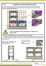
Page 34: ...he vertical spacing between the frames by fitting the mounting tool in two frames When mounting the 4 brackets screw the frame on the board in the hole for this purpose screw with stainless screws 6x40 10 2 b When assembling with 6 brackets place the top frame and place a middle bracket into place and screw on the board If there is no frame at the top screw the end bracket into its slot using stai...

Page 35: ... system 2 a When assembling 4 brackets screw the frame on the board in the hole provided for this purpose then screw the middle brackets into the slots with stainless screws 6x40 10 b When assembling 6 brackets place the top frame and place a middle bracket into place and screw on the board If there is no frame at the top screw the end bracket into its slot using stainless steel screws 6x40 10 THE...

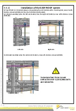
Page 36: ...e a frame on the third line to the right of the previous one Adjust the vertical spacing between the frames using the mounting tool in the middle brackets first right side and then left side place and screw the brackets with 6x40 stainless screws 10 b 6 bracket assembly placing and encasing two mounting tools between the two frames in the upper section of it and the two middle brackets to give the...

Page 37: ...ts always end up placing the end brackets with a mounting tool screw in with stainless screws 6x40 10 do the same for bottom end brackets a 4 bracket assembly place the left end bracket then the right end bracket screw with stainless screws 6x40 10 b 6 bracket assembly place the central end bracket screw with stainless screws 6x40 10 THE MOUNTING TOOLS CAN BE DISPLACED ON IF 4 OR 6 BRACKETS ARE MO...

Page 38: ...is the property of IRFTS It shall not be reproduced or shared with third party without agreement IRFTS Installation of the EASY ROOF system 7 Place and encase all other remaining frames to position in the PV field by repeating the operations on pages 35 to 37 38 9 4 2 Model M 1 60 Cells 6 Landscape ...

Page 39: ...em a Encase the tab of the second flashing into the first b Rotate the second flashing c Clip the second flashing with the other one Make a space of 3 mm between the two 2 Place other flashings fitting them into each other see beside Assembly of flashings 1 Position the first left flashing next to the first frame d For the high frieze option clip the support frieze at the top of the last flashing ...

Page 40: ...op of the frame 5 At the bottom cut the part of the flashing which exceeds the frame 6 Place a domed head screw 5 x 30 Inox b at each flashing overlap Tighten moderately 7 Place a domed head screw 5 x 30 Inox b centered on the oblong hole Tighten moderately VERY IMPORTANT unscrew one turn it is essential for the thermal expansion of the part 8 If there is no batten under the flashings overlap add ...

Page 41: ...a Encase the tab of the second flashing into the first b Rotate the second flashing c Slick the second flashing with the other Make a space of 3 mm between both flashings 2 Place other flashings by slotting on the previous ones see below Assembly of flashings 1 Position the first flashing on the right over the frame d For the high frieze option clip the support frieze at the top of the last flashi...

Page 42: ...ottom cut the part of the flashing which exceeds the frame of the first flashing if necessary 6 Place a domed stainless head screw 5 x 30 b in each flashing overlap Tighten moderately 7 Place a domed stainless head screw 5 x 30 b centered on the slot Tighten moderately VERY IMPORTANT unscrew one turn it is essential for the expansion of the part 8 If there is no batten under the flashings overlap ...

Page 43: ...rewed in with 6 x 40 stainless screws 10 9 4 5 1 Place all end brackets 9 at the bottom of the PV field using a mounting tool Encase each bracket in the holes on the frames 3 end brackets per frame align the bracket with help of the mounting tool screw in with 6 x 40 stainless screws 10 43 10 mm set 10 mm set Model M 1 60 Cells 6 Landscape THE USE OF A MOUNTING TOOL IS MANDATORY FOR THE end BRACKE...

Page 44: ... without agreement IRFTS Installation of the EASY ROOF system 9 4 5 44 Model M 1 60 Cells 6 Landscape 2 Install the deflectors at the top of the field under the end brackets placing as many deflectors at the top of the field as frames tab 3 On the left side of the system to optimize the tiles postion it is allowed to cut the ears 2 mm from the frame using a cutter 2 mm mini ...

Page 45: ... PV modules slightly to place the corresponding wedge to the size of the panel and then bear against the wedge Tightening torque 8 8 Nm 7 Place all middle brackets of the PV field 45 Model M 1 60 Cells 6 Landscape 2 Adjust the height of the support screws of the end clamp so that they are flush with the top of the PV module 3 Attach the PV modules at the bottom of the field with end clamps 5 or 16...

Page 46: ...n two modules the clamp leaning on the PV modules 2 Slide to encase it on the bracket 3 Slick the modules against the anti rotation wedge 4 Screw with screws CHc M6 x 30 12 or CHc M6 x 40 11 depending on the thickness of the PV module 3 Attach the PV modules at the top of the field with end clamps 5 or 16 with screw socket head cap M6 x 30 12 or M6 x 40 11 depending on thickness of the PV module S...

Page 47: ...rackets grounded during assembly See p 36 View with local section Glaw on the PV module Option 1 Connect the ground by connecting the middle brackets with the cable lugs and connect the ground to the PV module 2 Then ensure that the connection is made between the PV module and the middle bracket 6 and that this connection is less than 2 Ohms Option 2 Place the claw on the back of the PV module so ...

Page 48: ...ANT For tiles with high profile it is imperative to use a frieze for EASY ROOF system or a strip of adhesive foam before replacing the tiles dimension D For the tile overlap on the lateral flashings 2 and 3 the tiles should be tangent with the mark indicating Tile limit It is imperative that dimension D is 40 mm MAXI as shown in the diagram Tile limit mark 48 Model M 1 60 Cells 6 Landscape 10 mm m...

Page 49: ...ice This document is the property of IRFTS It shall not be reproduced or shared with third party without agreement IRFTS 49 1 Remove the detachable portion at the top of the frame Annex 1 Pyramid assembly A Flashing installation L shape left or right Model M 1 60 Cells 6 Landscape ...

Page 50: ...shared with third party without agreement IRFTS 50 2 Assemble and install the flashings as described on page 39 42 of the general instructions A Flashing installation L shape left or right Annex 1 Pyramid assembly 3 Cut the flashing from the bottom so that it covers the lower frame from 150 mm MINI 150 mm MINI 150 mm MINI Model M 1 60 Cells 6 Landscape ...

Page 51: ...ment is the property of IRFTS It shall not be reproduced or shared with third party without agreement IRFTS 51 B Flashings installation T shape left or right Annex 1 Pyramid assembly 1 Pull the detachable bottom part of the frame to the right or left as required Model M 1 60 Cells 6 Landscape ...

Page 52: ...on T shape left or right Annex 1 Pyramid assembly 2 Do the flashing flooring For the batten sizing refer to the general instructions on page 17 18 and 19 200mm 4 Position the batten inclined at 200 mm from the frame space needed for the lateral flashing sectional view of the frames 3 Extend the horizontal battens to ensure the flashing support under the frame 200mm sectional view of the frames Mod...

Page 53: ...greement IRFTS 53 B Flashings installation T shape left or right Annex 1 Pyramid assembly Assemble and install the flashings as described on page 39 41 of the general instructions 7 Cut the flashing down the column in alignment with the bottom of the frame 5 Position the flashing on top of the column 15 mm from the bottom of the frame see below 15mm 15mm Model M 1 60 Cells 6 Landscape ...

Page 54: ...hird party without agreement IRFTS 54 B Flashings installation T shape left or right Annex 1 Pyramid assembly 11 Also cover the top of the flashing in alignment with the edge of the last tile 8 Replace the tiles on the flashings 9 Place the roof flashings with respect to the MINI overlaps imposed in the general instructions on page 21 Model M 1 60 Cells 6 Landscape ...

Page 55: ...be reproduced or shared with third party without agreement IRFTS 55 B Flashings installation T shape left or right Annex 1 Pyramid assembly 11 Place the top frame to continue the installation according to guidelines of the general instructions for placing and securing the remaining elements of the system Model M 1 60 Cells 6 Landscape ...

Page 56: ...mension may vary between left and right depending on the space between the EASY ROOF frame and the fascia X must not be less than 10 mm The Y dimension must be adapted to cover what is necessary sectional view sectional view 10 mm MINI sectional view sectional view Attach the metal sheet to the side 10 mm MINI 5 mm set 5 mm set Attach the metal sheet to the side Section Model M 1 60 Cells 6 Landsc...

Page 57: ...nt to the limite tuile mark Optimal overlap and compliance with manufacturer s instructions 2 The tile is too long Trim it to align the tile s bottom with limite tuile mark view with local section Spot the limite tuile mark on the EASY ROOF frame 3 The tile is too short The tile must overlap the top flashing with a minimum of 150mm If the R dimension distance between the marking Limite tuile and t...

Page 58: ...lashing Model M 1 60 Cells 6 Landscape 1 In the case of a limited space in the direction of the slope it is possible to shorten the top of the frame from 80 mm MAXI under certain technical conditions At least 150 mm must be kept above the mark Limite tuile 2 Make a flashing between the ridge tiles and the EASY ROOF system by covering at least 150 mm of the frame from the Limite tuile marking Limit...

Page 59: ...reproduced or shared with third party without agreement IRFTS 59 Annex 4 Connection of the PV cables and grounding Model M 1 60 Cells 6 Landscape Ground wire into the module frame and the self taping screw into the bracket Cables coming from the attic between 2 layers of underlayment The cables directions must be towards the bottom earth ...

Page 60: ...reproduced or shared with third party without agreement IRFTS 60 Annex 4 Connection of the PV cables and grounding Model M 1 60 Cells 6 Landscape Ground every second brackets 1 bracket to ground 2 PV module Connect the from the inverter to of the first module Connect the ground wire to the frame of the module see manufacturer instruction ...

Page 61: ...rty of IRFTS It shall not be reproduced or shared with third party without agreement IRFTS 61 Annex 4 Connection of the PV cables and grounding Model M 1 60 Cells 6 Landscape Connect the modules together cable on cable Route the and the ground wirealong these cables so as not to loop them Go on the upper line ...

Page 62: ...the property of IRFTS It shall not be reproduced or shared with third party without agreement IRFTS 62 Annex 4 Connection of the PV cables and grounding Model M 1 60 Cells 6 Landscape Wire the final module of the line with the inverter line Connect the ground wire to the last frame of the last module ...

Page 63: ... shared with third party without agreement IRFTS 63 Annex 5 Assembly on long slope Model M 1 60 Cells 6 Landscape Number Definition Article Code 18 Middle Clamp Deflector A022V40 19 Black Middle Clamp Deflector A021V40N 20 Large Middle Clamp Deflector A022V40 21 Large Black Middle Clamp Deflector A021V40N Parts for long slope up to 15 m Optional parts ...

Page 64: ...is document is the property of IRFTS It shall not be reproduced or shared with third party without agreement IRFTS 64 Annex 5 Representation of parts Model M 1 60 Cells 6 Landscape 18 19 20 21 Deflector a part that is mounted perpendicular to the slope at the joining of the two modules ...

Page 65: ... applies to the PV field of over 12m in height slope irection 1 Assembly of middle brackets a 6 brackets assembly set in place and tighten the upper central middle bracket 4 brackets assembly set in place and tighten the upper right middle bracket b Use the deflector as a gage to position the other brackets For this insert the screws Ø 6 into holes Ø6 of each support bracket c Screw the middle bra...

Page 66: ...produced or shared with third party without agreement IRFTS 66 Annex 5 Assembly on large slope Model M 1 60 Cells 6 Landscape 2 Assembly of end brackets The assembly of the End brackets at the top of the field and bottom of the field is carried out as described on page 36 with the mounting tool provided for this purpose Left side Right side ...

Page 67: ...y without agreement IRFTS 67 Annex 5 Assembly on large slope Model M 1 60 Cells 6 Landscape 3 Middle Clamp Deflector assembly b Screw and tighten all Middle Clamp Deflector with the Chc M6x30 12 or Chc M6x40 11 depending on the thickness of the PV module For PV module with a width lower than 992mm use Large Middle Clamp Deflector a Position the wedges on the middle brackets ...

Reviews: