background image

ICU7000-2

CONTROLS UP TO

2 iCAMs

EASY

INSTALLATION

ICU7000-2 

HARDWARE GUIDE

I D E N T I T Y   C O N T R O L L E R

• Supports all iCAM7 series Camera Units
• iCAM4000 series Support Available
• Easy Installation
• Surface Mount Installation

 VERSION 1.0

Packing List

Required Equipment (not included)

Hardware Components

•  iCAM7 series Camera unit (sold separately)
•  Windows Compatible computer (Refer to the iData 
    EAC Software Manual for details)

Network

•  Ethernet Switch (an Ethernet Hub is not acceptable)
•  Ethernet Wiring - CAT5e or better with RJ45 connectors

Software

•  iData EAC Software version 3.11.x or above (Refer to the iData EAC Software Manual for details)

Power Source (optional)

•  External power source - 12-24 VDC +/- 10% / Minimum 24W (12VDC @ 2AMPS)
    (Measured at ICU7000-2 unit)
•  Uninterruptible Power Supply (strongly recommended)

What’s in the Box

•  ICU7000-2 - Identity Controller Unit
•  Power Adapter
               Input: 100-240VAC @ 1.0AMP 50/60Hz
               Output: 12VDC - 2.5AMPS
•  Power Cable (110 VDC)
•  Grommet
•  Keys (x2)
•  Hardware Guide

Summary of Contents for IrisAcces ICU7000-2

Page 1: ... the iData EAC Software Manual for details Network Ethernet Switch an Ethernet Hub is not acceptable Ethernet Wiring CAT5e or better with RJ45 connectors Software iData EAC Software version 3 11 x or above Refer to the iData EAC Software Manual for details Power Source optional External power source 12 24 VDC 10 Minimum 24W 12VDC 2AMPS Measured at ICU7000 2 unit Uninterruptible Power Supply strong...

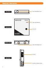
Page 2: ...2 Front View Top View Hardware Information Cable Channel Knock out Cable Channel Knock out Case Lock Power Light Indicator Air Vent Bottom View Side View Model Serial Number Label ...

Page 3: ...stallation location requires power and a network communication to the IrisServer and iCAM7 series unit s If used with an access control panel the ICU can reside close to the access panel It is suggested that the ICU be on the same physical network switch as the iCAM s which it controls This is to maintain communication between the ICU and the iCAM so that the iCAM can remain operational All system...

Page 4: ...he location of installation holes There are two types of screw holes the diameter of one type is 10m 0 39 inch and the other type is 5mm 0 20 inch 5 Drill or punch holes in the mounting surface on the marks 6 Insert the cables into the enclosure 16 0 62 245 9 6 72 2 8 76 3 220 8 7 89 3 5 65 2 6 65 2 6 NOTE Power Adapter The included power adapter can be used as the power source for the ICU Be sure...

Page 5: ...the NEMA 5 US type then a local type power cable with a C13 power connection must be purchased and used for installation Ethernet Connection An Ethernet network connection is required between the ICU and the IrisServer computer when performing a New Installation Upgrade or Configuration of the ICU software This Ethernet connection should remain at least until the ICU configuration is completed For...

Page 6: ...B C D F E A B C D E GPIO Specifications For output the GPIO can provide 5VDC 20mA For Input the GPIO is selectable between active High active Low Assignment of GPIO is handled through Software External GPIO GPIO1 GND GPIO2 GND GPIO3 GND GPIO4 GND ...

Page 7: ...port of computer or access system TX RX TX RX RS485 serial communication port for connection with an access panel or to other computer equipment When configured the Card ID associated with the user is output from the RS485 output port upon a successful identification TX RX TX RX GND RS422 Output RS422 Output To RS422port of computer or access system TX TX RX RX RS422 serial communication port for ...

Page 8: ...ich changes from Red to Green for an accepted user Relay_2 NC_2 COM_2 NO_2 is typically used to indicate iCAM tamper In this diagram the relay is activated when the iCAM tamper switch is triggered The maximum electrical rating for the relay is 3A at 24VDC RED LIGHT POWER SUPPLY ALARM SYSTEM 24 HOUR ZONE GREEN NC_1 COM_1 NO_1 NC_2 COM_2 NO_2 Wiegand Output Wiegand Specifications Wiegand output uses...

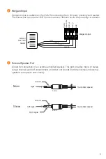
Page 9: ...um 300mA current to a proximity card reader 12VDC Max 0 3A DATA_0 DATA_1 GND External Speaker Out F To amplified speaker Left signal Ground Right signal 3 5mm Allows for connection of an external amplified speaker This port provides mono or stereo single channel audio of voice prompts and other unit sounds Both the internal and external speakers can operate concurrently To amplified speaker Mono S...

Page 10: ...em Additional documentation for setup and configuration can be found at http irisid com productdocumentation How to access the ICU7000 2 Configuration interface NOTE The IP address of the ICU7000 2 can be audibly announced by pressing the Factory Default button twice consecutively located on the ICU main board IMPORTANT IF THE BUTTON IS HELD DOWN CONTINUOUSLY FOR 3 OR MORE SECONDS THE ICU7000 2 IP...

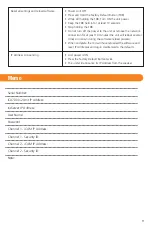
Page 11: ...DB Turn ON the unit power Keep the FDB held in for at least 10 seconds Stop holding the FDB Do not turn off the power to the unit or remove the network connection for at least 10 minutes the unit will reboot several times on its own during the software reload process When complete the ICU will have reloaded the software and reset IP Addresses and log in creditenials to the defaults IP Address Anno...

Page 12: ...dity Ethernet LAN WAN Communications 2 Remote Channel Wiegand In Out Dry Contact Relay x 2 Programmable GPIO x 4 RS422 x 2 Inputs Outputs CE FCC KCC UL294 Certifications Iris ID Systems Inc www irisid com 7 Clarke Drive Cranbury NJ 08512 USA Tel 609 819 IRIS 4747 Fax 609 819 4736 2015 Iris ID Inc All rights reserved Design and specification subject to change without notice Printed in Korea Additio...

Reviews: