background image

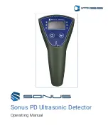
Sonus PD Ultrasonic Detector

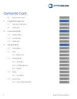
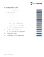
5

  11.5.2 

Combined 

Functionality

12 

Check Sonus PD Function


12.1 

Function Tester


12.2 

Check The TEV Function


12.3 

Check The AE Function

13 

Surveying Switchgear Panels For PD- TEV


13.1 

Step 1- Check TEV Activity Levels


13.1.1  Example 1 – Component Switchgear


13.1.2  Example 2 – Fully Enclosed Switchgear


13.2 

Step 2- Verify Whether Detected Activity is Noise or PD

14 

Surveying Switchgear Panels For PD- TEV


14.1 

Step 1- Check Acoustic Emissions 

Activity Levels

15 

Appendix A: Example Test Sheet

16 

Appendix B: The Relationship Between PD and Criticality


21


22


21


21


23


24


24


23


25


26


26


27


28


19

Contents Cont.

Summary of Contents for Sonus PD

Page 1: ...Operating Manual Sonus PD Ultrasonic Detector ...

Page 2: ...07 9128 E mail info iriss com Web http www iriss com 2017 IRISS Inc All rights reserved The contents of this manual are copyrighted property Duplication and distribution in any form particularly reprinting photographic mechanical or electronic reproduction or in the form of storage in data processing systems or data networks is prohibited without the consent of the copyright holder Revision 1 0 Da...

Page 3: ...ons Of Sonus PD 3 1 Dimensions 3 2 Weight 3 3 Power Supply 3 4 Temperature 3 5 Relative Humidity 3 6 IP Rating 4 CE Compliance 5 Sonus PD Kit List 6 General Substation Safety Precautions 6 1 Access 6 2 Visual Inspection Of Substation 7 Environmental Protection 8 Sonus PD Overview 8 1 Sonus PD Outline 07 06 07 07 08 08 08 08 08 08 08 10 10 11 11 11 10 09 09 Contents ...

Page 4: ...Surface Tracking 10 2 Acoustic Sensor 10 3 Specification 11 Operational Control 11 1 Control Buttons 11 2 Power 11 2 1 Battery Level 11 3 Operating Modes 11 3 1 TEV Modes 11 3 2 TEV Noise Detection 11 3 3 AE Mode 11 4 Display 11 4 1 Level Display 11 5 Sonus PD App 11 5 1 Sonus PD App Introduction 11 13 13 13 13 14 14 15 14 14 16 16 15 19 17 17 12 12 19 Contents Cont ...

Page 5: ...tep 1 Check TEV Activity Levels 13 1 1 Example 1 Component Switchgear 13 1 2 Example 2 Fully Enclosed Switchgear 13 2 Step 2 Verify Whether Detected Activity is Noise or PD 14 Surveying Switchgear Panels For PD TEV 14 1 Step 1 Check Acoustic Emissions Activity Levels 15 Appendix A Example Test Sheet 16 Appendix B The Relationship Between PD and Criticality 21 22 21 21 23 24 24 23 25 26 26 27 28 19...

Page 6: ...y A colour coded traffic light system indicates when detected levels exceed the pre set thresholds The Sonus PD has a built in TEV sensor for capacitive coupling to switchgear and a built in ultrasonic sensor for detection of surface discharge and tracking Headphones are also supplied to help the user when working in noisy environments The Sonus PD is supplied with a battery operated Function Test...

Page 7: ... the equipment is in operation failure can be avoided A PD event will radiate energy in different forms and this energy can be picked up by the Sonus PD in order to detect the source and locate it PD creates EM radiation that dissipates in all directions away from the source Metal components for instance the panels around switchgear will pick up this radiation and small voltages called Transient E...

Page 8: ... is included in the kit The Sonus PD Field Detector can be used in the following temperature ranges Operation 0 C to 55 C Storage 20 C to 75 C 3 5 Relative Humidity The Field Detector can be used in the following relative humidity ranges Operation 0 to 90 3 4 Temperature The SONUS PD is IP54 rated but is not intended for use in damp conditions 3 6 IP Rating Test Situation Est Battery Life Sonus PD...

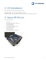
Page 9: ...Emission Standard Residential Commercial and Light Industry Environment 4 CE Compliance The Sonus PD Kit includes 1 x Sonus PD 1 x Sonus PD power supply charger unit 1 x USB Charger Cable 1 x Car Charging Adapter 1 x 3 5mm stereo headband Headset 1 x PD FT Function Tester 1 x Moulded carry case 1 x Sonus PD Manual 1 x Sonus PD Companion App Manual 5 Sonus PD Kit List ...

Page 10: ...fety rules at all times The following safety rules which are particular to the Sonus PD equipment should be applied in addition to the existing safety rules which are required by the plant owner General safety rules for the use of the Sonus PD are as follows 1 Avoid working alone 2 Only authorized personnel with appropriate Health and Safety Training should use the equipment 3 Do not use the equip...

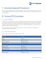
Page 11: ...el An OLED type screen is used for function control and providing both text and graphical output information to the user In addition the SONUS PD has an audio output through both a built in speaker and 3 5mm earphones jack The unit is powered by a lithium ion battery giving a long life for hours of use The software has intelligent power management prolonging battery life further 8 1 Sonus PD Outli...

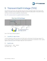
Page 12: ...enerally only present in equipment rated above 2 500 Volts Fig 2a TEV PD pulse propagation equipment The built in Capacitive Coupler sensor detects TEVs as they pass over the cladding of the high voltage equipment The very fast transient signals are detected by the Sonus PD and their magnitude measured and displayed A noise cancelling algorithum inside the Sonus PD unit seperates background noise ...

Page 13: ...Heat from the sparks causes carbonisation of the insulation and leads to the formation of permanent carbon tracks on the surface Under such conditions this process will develop over time and eventually lead to flashover and full breakdown of the insulation 10 1 Surface Tracking The ultrasonic acoustic Sensor is designed for use on air insulated terminations where there is a clear sound path betwee...

Page 14: ...he POWER button is used to turn the Sonus PD ON and OFF By pressing the button once the instrument will toggle between these states Note that the POWER button should be pressed and held down for two seconds before the power is switched 11 2 Power The remaining charge in the battery is indicated by the small icon in the bottom right hand side of the display screen 11 2 1 Battery level ...

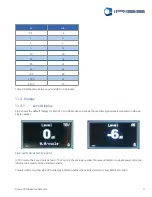
Page 15: ... modes 11 3 Operating Modes In TEV Mode the instrument measures and displays the magnitude of TEV signals detected The measured value is shown in dBmV such that 0dB 1mV The relationship between detected signal magnitude in dB and mV is shown in the Table below 11 3 1 TEV Mode mV dB 1 0 2 6 5 14 10 20 20 26 35 31 50 34 100 40 1 000 60 10 000 80 Table 1 Relationship between mV and dB for TEV signals...

Page 16: ... to signals with a magnitude greater than 20dB as noise signals below this level are relatively common It should be noted that when high noise is detected it can mask genuine TEV It is advisable to use more sophisticated PD detection instruments that can detect PD even in the presence of high noise In AE Mode the instrument measures and displays the magnitude of ultrasonic acoustic signals detecte...

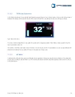
Page 17: ...th TEV and AE Modes and shows the real time signal levels measured in dB as a single number 11 4 1 Level Display Fig 5 LEVEL Mode for TEV and AE In TEV mode the Count is also shown The Count is the average number of pulses detected in a single power cycle and reflects the intensity of the detected activity Coloured LEDs on either side of the display indicate whether the activity detected is Low Me...

Page 18: ...h 29dB Thresholds for TEV measurements are set according to the levels shown in the table below Thresholds for AE measurements are set according to the levels shown in the table below Table 3 TEV activity level thresholds Table 4 AE activity level thresholds Low 20dB Medium 20 29dB High 29dB ...

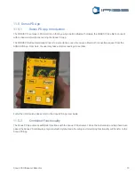
Page 19: ...tion request from the SONUS PD App From here the user may take and store readings in real time 11 5 Sonus PD App 11 5 1 Sonus PD App Introduction For further information please refer to the Sonus PD App User Guide The Sonus PD App unlocks additional functions with the Sonus PD Instrument Once the Instruments and App have been paired the Sonus PD will display only a Bluetooth Symbol and all reading...

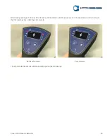
Page 20: ...dings the Sonus PD will seek synchronization with the power cycle in the substation in order to ensure that the readings it is collecting are accurate Not Synchronized Synchronized The synchronization status will also be displayed on the mobile app ...

Page 21: ... LED will be bright and when fully charged the LED will return to normal intensity 12 1 Function Tester With the Sonus PD in TEV mode hold the PD FT up against the sensor head of the Sonus PD and press the blue button as shown in Fig 10 below The bottom surface of the PD FT should be held directly against the sensor head The Sonus PD should record noise value of greater than 30dB to confirm correc...

Page 22: ...hown in Figure 11 below The AE sensor end of the PD FT should be held up against the sensor head using the two rubber extensions to regulate the distance between the PD FT and the Sonus PD as shown in the picture The Sonus PD should record a value of greater than 30dB to confirm correct operation 12 3 Check The AE Function Fig 11 Testing AE function with PD FT ...

Page 23: ...hown on the Sonus PD screen b If a single switchgear unit has more than one metal panel then the test should be carried out on each of them individually 1 Record the results for future reference and comparison An example of a form for doing this is shown in Appendix A 13 1 Step 1 Check TEV Activity Levels Fig 12 Checking activity levels on each panel Note Always maintain Safety Distances between t...

Page 24: ...he diagram in Figure 13 13 1 1 Example 1 Component Switchgear Fig 13 Sonus PD placement on Component switchgear Where the switchgear has enclosed components such as the bus bar chamber CT or VT chamber circuit breaker and cable box then each part should be tested for activity as shown in the diagram in Figure 14 13 1 2 Example 2 Fully Enclosed Switchgear Fig 14 Sonus PD placement on fully enclosed...

Page 25: ...evel of activity on the switchgear panel 2 Measure background noise in the substation by placing the Sonus PD sensor up against a metallic object that is not electrically coupled to the switchgear under test This will give a background reference level 3 If the activity level measured on the switchgear is more than 6dB higher on the switchgear than it is on the reference object then there is a high...

Page 26: ...ean aiming the sensor though gaps in the metal cladding or through ventilation grills or through dedicated ultrasound ports b If activity is found move the transducer around until the highest level is detected and record the dB level shown on the Sonus PD screen 3 Record the results for future reference and comparison An example of a form for doing this is shown in Appendix A 14 1 Step 1 Check Aco...

Page 27: ...on Name Test Engineer Location Test Date Panel No Panel Section TEV Level dB Acoustic Level dB 1 Top Middle Bottom 2 Top Middle Bottom 3 Top Middle Bottom 4 Top Middle Bottom 5 Top Middle Bottom 6 Top Middle Bottom 7 Top Middle Bottom 8 Top Middle Bottom 9 Top Middle Bottom ...

Page 28: ...ndication of weak insulation and an increased probability of failure Both the magnitude and repetition rate are important in determining the influence of the PD and the following table is based upon the average total discharge activity per power cycle The table below is a guide to PD activity levels and the associated severity Partial Discharge Low No further action required Medium Test again with...

Reviews: