background image

Page 2

Fig

. 1

BEEP

DATA 1

+12V

LED R

LED G

DATA 0

GND

Fig

. 3

Fig

2

Fig

. 4

BEEP

DATA 1

+12V

LED R

LED G

DATA 0

GND

MATRIX II MF-I

www.ironlogic.

me

Holes 
to feed 
the cable 
through 

mm

mm

mm

mm

mm

LED

Plugs

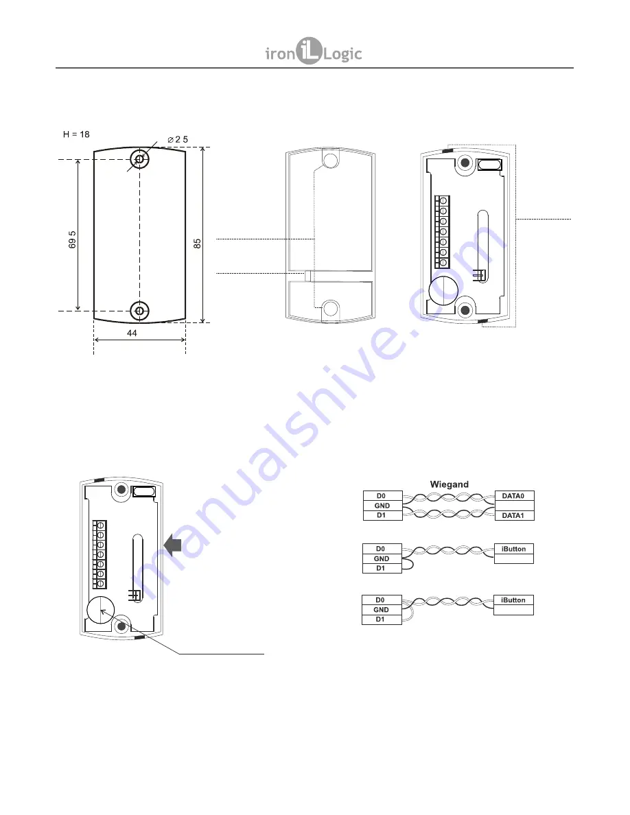
Socket terminals:

1. Power 12 V 
2. Common ground (-)
3. DATA0 output
4. DATA1 output
5. LED-G (external control for green LED)
6. LED-R (external control for red LED)
7. BEEP (external control for the buzzer)

To increase buzzer volume, 
remove this sticker

Reader

ACS Controller

iButton (DS1990A emulation)

iButton (One-time transmission)

Common

Common

Common

Fig

. 5 

Connecting the reader to ACS controller.

CONNECTION LAYOUT

Summary of Contents for Matrix II MF-I

Page 1: ...red place and fix it with screws 5 Close the reader case openings with plugs Fig 2 Note 1 Do not install readers closer than 10 cm one from another Note 2 To avoid electrical interference when connecting the reader to the controller a UTP cable is recommended such as CAT5e UTP cable see Fig 5 3 OPERATION Reader operation without external indication control 1 When power is supplied in standby mode ...

Page 2: ...ket terminals 1 Power supply 12 V 2 Common ground 3 DATA0 output 4 DATA1 output 5 LED G external control for green LED 6 LED R external control for red LED 7 BEEP external control for the buzzer To increase buzzer volume remove this sticker Reader ACS Controller iButton DS1990A emulation iButton One time transmission Common Common Common Fig 5 Connecting the reader to ACS controller CONNECTION LAY...

Page 3: ...R terminals 2 Power on the reader 3 If the LED is blinking red and asignal is sounding the reader is already in Protected Mode 4 If the LED is shining solid red touch the reader with the IronLogic Object card The reader changes LED colour to green and issues a beep for 1 second The Object card has now been stored into reader as a Master card 5 Power off the reader 4 1 2 Storing Object Cards Up to ...

Page 4: ...ls The reader will confirm the parameter choice and will switch into indicating parameter value 5 Indicating parameter value is similar to indicating parameter number but instead of LED flashing red it s flashing green Parameter values start with the current parameter value 6 To confirm the currently active parameter value connect LED G and GND terminals The new value is stored 7 Power off the rea...

Page 5: ...Mifare Ultralight Mifare ID Mifare Standard Classic 1K and 4K Card key fobs reading distance 2 6 cm Output protocol iButton Dallas Touch Memory Wiegand Line distance from controller via iButton protocol up to 15 m via Wiegand protocol up to 100 m Card reading status indication visual bicoloured LED audial buzzer Indication control internal external Power supply voltage 12 V DC Current in Card Stan...

Page 6: ...d production AVS LLC 7 Bobruiskaya street Saint Petersburg 195009 Russian Federation E mail marketing rfenabled com Phone 78122411853 78125421185 www ironlogic ru Authorized representative in the European Union SIA IRONLOGIC 79A Slokas iela LV 1007 Riga Latvia E mail info ironlogic lv headstaff ironlogic lv Phone 37166181894 37124422922 www ironlogic me Page 6 MATRIX II MF I www ironlogic me The s...

Reviews: