www.desatech.com www.ironhaus.com
123126-01A
11
PREInStaLLatIOn PREPaRatIOn
Continued
6. Using screws or nails, secure fireplace to
framing through flanges located on sides
of fireplace.
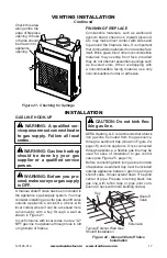
WARNING: When finishing
appliance, do not overlap com
-
bustible material onto the black
front face. Brick, tile or other
noncombustible materials may
be applied to the face provided
that any gap is between the
material used and the face is
caulked with a noncombustible
caulking.
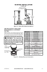
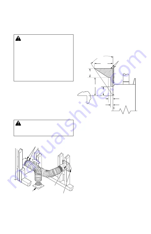
OPTIONAL OUTSIDE AIR KIT
(MODEL AK4/AK4F)
Installation of an outside air kit should be
performed during rough framing of fireplace
due to the nature of it's location. Outside com-
bustion air is accessed through a vented crawl
space (AK4F) or through a sidewall (AK4).
See
Figure 39 on page 32 for instruction of
operating air kit.
CAUTION: Combustion air
inlet ducts shall not terminate
in attic space.
3" (7.6 cm)
1
1
/
2
"
(3.8 cm) Max.
8"
6" (15.2 cm)
14"
12"
(22.9 cm)
Combustible
Materials
30°
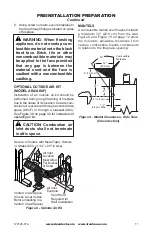
Figure 9 - Mantel Clearances - Side View
(Cross Section)
Figure 8 - Outside Air Kit
Secure to Collars with Metal Tape, Screws
or Straps (Min. of 1/4" x 20" in size)
Air Inlet
Location
Must Allow
For Bushes
or Snow
Vent Hood
Required for
Wall Installation
Air Inlet
Eyebrow
Vented Crawl Space
(Check Local Codes
Before Installing in a
Vented Crawl Space)
MANTELS
A combustible mantle shelf maybe installed
a maximum 12" (22.9 cm) from the wall.
Figure 9 and Figure 10 on page 12 show
the minimum allowable distances from
various combustible mantle components
in relation to the fireplace opening.


