P
AGE
12
A
SSEMBLY
I
NSTRUCTION
A
SSEMBLY
S
TAGE
#6
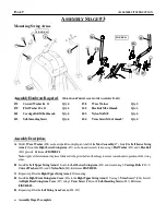
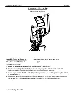
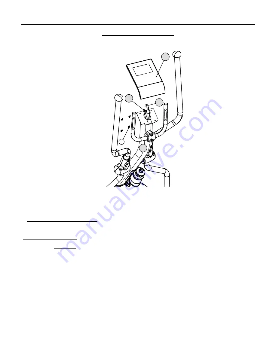
Mounting Computer
Assembly Hardware Required
:
(*H
ARDWARE
P
REINSTALLED
IN
THE
A
SSEMBLY
P
ARTS
)
#44
Truss Screw M5 x 14mmL*
Qty. 4
Assembly Description:
A) Remove the preinstalled mounting hardware from the back of the Computer (#27)
.
B)
Plug the connector of
Upper Data Cable
(#8) into the corresponding receptacle on the back of the
Computer
(#27).
Note:
Avoid pulling on (stretching) the cable assemblies in order to make computer connections.
C)
Connect the
plug end of the
Heart Rate Cable
(#22) into the receptacle end of the of the cable (pigtail) coming from the back
of the
Computer
(#27).
D)
Tuck excess cable lengths down into the mast and place the
Computer
(#27)
on top of the mounting plate.
Align and secure
the
Computer
(#27) to the
Computer Mast Assembly
(#7) mounting plate using the 4-
Truss Screws
(#44).
♦
Assembly Stage #6 complete
44
7
8
22
27


