A
SSEMBLY
STAGE
#2
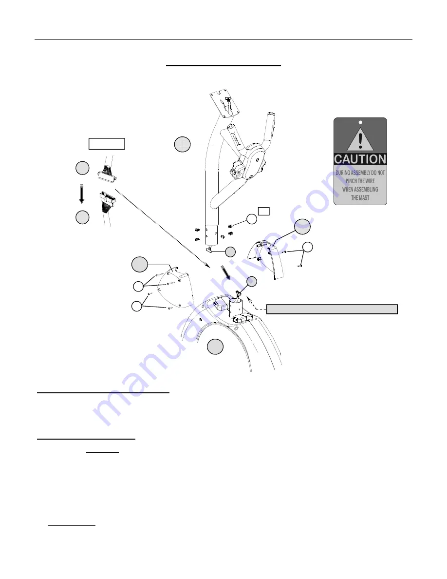
Attach Handlebar Mast Assembly
Assembly Hardware Required:
(*H
ARDWARE
P
REINSTALLED
IN
THE
A
SSEMBLY
P
ARTS
)
#36
Button Head Allen 3-1 Bolt*
Qty. 5
#38
Self-Threading Screw
Qty. 2
#37
Self-Threading Screw
Qty. 4
Assembly Description:
(We Recommend 2-Person Assembly)
A)
Remove the preinstalled mounting hardware (5-
Button Head 3/1 Bolts
#36 ) from the
Handlebar Mast Assembly
(#4).
B)
Connect the
Upper Data Cable
(#5) to the
Lower Data Cable
(#6) as shown in
FIGURE #1
.
C)
Tuck the cable lengths inside the frame tubes and insert the end of the
Handlebar Mast Assembly
(#4) down onto the
Base
Assembly
(#1). Align the mounting holes and secure the mast assembly in place using 5-
Button Head –3/1 Bolts
(#36).
D)
Attach the
Left & Right Mast Covers
(#7 & 8) using a combination; 4-
Self Threading Screws
(#37) and 2-
Self Threading
Screws
(#38) following the orientation shown.
Assembly Note
: Use caution when assembling the mast to the main base. Cables can be pinched if they are not properly routed.
♦
Assembly Stage #2 completed
A
SSEMBLY
I
NSTRUCTION
P
AGE
7
37
36
8
FIGURE #1
4
5
6
7
Cable Pinch Point: Use Caution During Assembly
x5
37
38
5
6
1


