background image

REF# Keys Part #

DESCRIPTION

QTY.

REF# Keys Part #

DESCRIPTION

QTY.

A1

323-00156 MAIN FRAME

1

B1

323-00111 CONSOLE TUBE

1

A2

311-00009 MAGNETIC FLYWHEEL

1

B3

310-00121 WATER BOTTLE

1

A3

302-00159 FLAT WASHER

2

B5

307-00130 UPPER ELECTRONIC WIRE, 420E

1

A4

302-00150 NUT

2

B6

313-00075 PULSE WIRE

2

A5

311-00042 TENSION PULLEY

1

B7

302-00154 BOLT

2

A6

302-00151 SPACER

4

B8

302-00157 BUSHING

2

A7

302-00152 FLAT WASHER

4

B9

330-00020 SHAFT

1

A8

302-00175 SCREW

4

B10

331-00032 BEARING

4

A9

331-00026 BEARING

4

B11

302-00158 BUSHING

4

A10

302-00208 E CLIP

3

B12

323-00131 CONNECT TUBE

1

A11

323-00133 MAGNETIC HOUSING

1

B13

302-00165 FLAT WASHER

8

A12

302-00170 NUT

1

B14

302-00204 SPRING WASHER

8

A13

302-00176 SCREW

1

B15

302-00186 SCREW

2

A14

302-00202 SPRING

1

B16

306-00294 BOTTLE HOUSING

1

A15

307-00029 MOTOR

1

B17

302-00187 SCREW

5

A16

302-00171 NUT

1

B18

306-00232 DECORATION BOTTLE HOUSING A

1

A17

302-00212 SUPPORT BRACKET

1

B19

306-00233 DECORATION BOTTLE HOUSING B

1

A18

302-00177 SCREW

1

B20

302-00198 SCREW 1

A19

302-00213 SUPPORT BRACKET

1

B21

302-00188 SCREW

6

A20

302-00178 SCREW

1

B22

302-00166 FLAT WASHER

2

A21

302-00203 SPRING

1

C1

323-00135 REAR STABILIZER

1

A22

304-00010 BELT

1

C2

306-00212 END CAP

2

A23

311-00023 BELT PULLEY

1

C3

306-00298 END CAP COVER

2

A24

330-00042 PULLEY AXLE

1

C4

302-00189 SCREW

2

A25

302-00179 SCREW

4

C5

302-00167 FLAT WASHER

2

A26

302-00160 FLAT WASHER

4

C6

302-00205 SPRING WASHER

2

A27

302-00172 NUT

4

C7

302-00173 NUT CAP

2

A28

302-00211 MAGNET

1

D1

323-00104 FRONT STABILIZER

1

A29

311-00025 TURNING PLATE

2

D2

306-00213 END CAP

2

A30

302-00180 SCREW

2

D3

306-00298 END CAP COVER

2

A31

306-00336 DECORATION CAP

2

D4

306-00300 TRANSMIT WHEEL HOUSING

2

A32

319-00004 PIPE

2

D5

302-00190 SCREW

4

A33

331-00038 BEARING

4

D6

306-00301 TRANSPORTATION WHEEL

2

A34

302-00161 FLAT WASHER

2

D7

302-00191 SCREW

2

A35

306-00226 SCREW COVER

2

D8

302-00168 FLAT WASHER

2

A36

302-00181 SCREW

2

D9

302-00206 SPRING WASHER

2

A37

323-00108 PEDAL TUBE (RIGHT)

1

D10

302-00174 NUT CAP

2

A38

323-00109 PEDAL TUBE (LEFT)

2

E1

307-00090 CONSOLE

1

A39

302-00023 BOLT

2

E2

313-00011 AC ADAPTER

1

A40

302-00162 FLAT WASHER

2

F1

323-00129 PULSE HANDLEBAR

1

A41

302-00163 FLAT WASHER

2

F2

302-00025 SUPPORT BRACKET

1

A42

302-00182 SCREW

2

F3

302-00193 SCREW

2

A43

323-00116 CONNECT PIPE

2

F4

310-00103 FOAM GRIP

2

A44

302-00183 SCREW

1

F5

313-00015 PULSE GRIP w/ WIRE

2

A45

313-00076 SENSOR WIRE

1

F6 

302-00194 SCREW

2

A46

302-00209 FIXING HOUSING

1

G1

323-00155 HANDLEBAR

2

A47

305-00010 RIGHT COVER

1

G2

310-00098 FOAM GRIP

2

A48

306-00296 DECORATION COVER

1

G3

306-00228 END CAP

2

A49

305-00009 LEFT COVER

1

G4

302-00195 SCREW

2

A50

306-00297 DECORATION COVER

1

H1

306-00241 DECORATION COVER A

1

A51

302-00200 SCREW COVER

8

H2

306-00242 DECORATION COVER B

1

A52

302-00164 FLAT WASHER

8

H3

306-00218 PEDAL JOINT COVER A

1

A53

302-00184 SCREW

3

H4

306-00219 PEDAL JOINT COVER B

1

A54

302-00215 TAPPING SCREW

6

H5

306-00214 PEDAL LEFT

1

A55

313-00074 POWER WIRE

1

H6

306-00299 PEDAL RIGHT

1

A56

302-00201 SCREW FOR MOTOR

4

J1

302-00155 BOLT

2

A57

302-00072 TENSION CABLE

1

J2

302-00196 SCREW

4

A58

302-00214 SUPPORT BRACKET

1

J3

302-00197 SCREW

4

A59

302-00185 SCREW

2

J4

302-00156 BOLT

4

A60

319-00218 U BRACKET 30, 320E/420E

2

J5

302-00169 FLAT WASHER

4

A61

302-01225 BUSHING, 18X11.5MM

4

J6

302-00207 SPRING WASHER

4

A62

302-00165 FLAT WASHER, M8X16X1.2T

4

J7

302-00210 KNOB

4

A63

302-01224 SCREW, M8X50L

2

K1

302-00319 BOLT PACK

1

A64

302-00370 M8 LOCKNUT

2

K2

315-00013 OWNER'S MANUAL

1

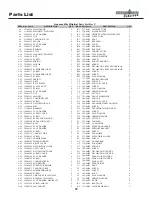
Ironman 420e Elliptical Parts List Rev C

Parts List

20

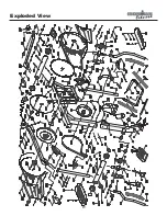
Summary of Contents for 420E

Page 1: ...Owner s Manual IRONMAN 420e ELLIPTICAL Customer Service 1 800 750 IRON 1 800 750 4766 Ironman Fitness 4009 Distribution Drive Suite 250 Garland TX 75041 www ironmanfitness com 315 00043 11 05 Rev A 420e ...

Page 2: ...nts 2 Important Safety Information 3 Before You Start 4 Assembly 5 9 Console Instructions 10 14 Monitoring Your Heart Rate 15 16 Moving Instructions 17 Warm Up Exercises 18 Exploded View 19 Parts List 20 Warranty 21 ...

Page 3: ...onman Fitness recom mends a mat be placed under the unit to protect floor or carpet and for easier cleaning 4 Follow safety information in regards to plugging in your unit Do not run the power cord underneath your unit Do not operate the unit with a damaged or frayed power cord 5 Wear comfortable good quality walking or running shoes and appropriate clothing Do not use the unit with bare feet sand...

Page 4: ...ur exercise heart rate If you have heart problems you are not active and or are over the age of 35 years do not use the pre set pro grams or start an exercise program without first contacting and receiving approval from your physician To avoid the risk of electrical shock always keep the console dry Do not spill liquids on the console Ironman Fitness recommends a sealed water bottle for beverages ...

Page 5: ...EN WRENCH 2 PHILLIPS SCREW DRIVER 3 WRENCH Main Components 1 OWNER S MANUAL 2 MAIN FRAME 3 HANDLEBARS LEFT AND RIGHT 4 PULSE HANDLEBARS 5 REAR STABILIZER 6 FRONT STABILIZER 7 MAIN SUPPORT TUBE 8 PEDALS LEFT AND RIGHT 9 CONSOLE Hardware 1 SCREW M8X90MM Qty 2 2 FLAT WASHER M8X16X1 2T Qty 10 B13 B22 3 SPRING WASHER M8 Qty 2 B14 C6 4 SCREW Qty 2 5 FLAT WASHER Qty 2 6 SPRING WASHER Qty 2 7 SCREW M8X15M...

Page 6: ...stabiliz er Using this hardware attach the front stabilizer to the main frame Assembly 6 Figure 2 Figure 1 FIGURE 3 Step 1 Remove the Bolts B21 Spring Washers B14 and Washers B13 from the Central Support Tube Connect the Lower Cable Assembly B5 to the Upper Cable Assembly A15 Note Make sure that cables are not pinched Step 2 Connect the Central Support Tube B onto the Main Frame A using hard ware ...

Page 7: ... place using Screws E4 FIGURE 5 Step 1 Pull Right Connect Tube A43 Match up bolt holes see Figure 5a Secure with Bolt J1 Step 2 Remove the Bolts G4 from the Handlebars G Slide Handlebar onto Central Support Tube Line up bolt holes see Figure 5a Replace hard ware Step 3 Repeat Assembly steps for Left side Figure 4 Figure 5 Figure 5a ...

Page 8: ...IGURE 7 Step 1 Remove the Bolts B7 from the Central Support Tube B Remove the Screw F3 from the handlebar clip Step 2 Connect Cables F5 to Sensor Wires B6 Step 3 Slide the Handlebars F into the Central Support Tube Twist the Handlebars to bring them into the cor rect position Secure Handlebars with Bolts B7 and Screw F3 Note Be careful not to pinch the wires Figure 7 ...

Page 9: ...peat for Left Side Pedal Covers Step 2 Assemble Left and Right Pedals H5 H6 to Main Frame using Bolts J4 Washers J5 Spring Washers J6 and Star Knobs J7 Note There are three pedal positions on moving track Assembly 9 Congratulations You have completed the assembly of your new Ironman 420e Elliptical ...

Page 10: ...ode this button is used to display TIME SPEED DISTANCE CALORIE RPM WATT or PULSE in the large display window In Body Fat Mode this button to scroll thru results DIAL This button is used to select the program you want to use during your workout This button is used to increase or decrease TIME DISTANCE CALORIES HEIGHT WEIGHT AGE SEX and PULSE This button is used to increase or decrease the resistanc...

Page 11: ...to zero CALORIES This will count the accumulated calorie consumption during a workout If you enter a preset target the console will count from the amount set down to zero Note This data is an estimate only and should be used as a comparison over several exercise sessions WATT Measure of energy created while you pedal USER Displays User START STOP Displays START or STOP PROGRAM Displays current exe...

Page 12: ...setting You can only change user settings in the STOP mode MANUAL PROGRAM Program 1 Allows the User to manually adjust tension settings throughout their workout The default tension level is 6 You may set Time or Distance for your workout After User number is selected Turn Dial until P1 shows on display Press Enter The Time will now flash in display window Turn the Dial to increase or decrease the ...

Page 13: ...splay Press Enter to select this program The TIME DISTANCE and CALORIES will flash in display Turn Dial to select TIME DISTANCE and CALORIES Press Enter after each selection Column 1 will now be flashing Use the Dial to set Tension setting for first segment Press Enter to confirm your setting Column 2 will now be flashing Use the Dial to set Tension for second segment Press Enter to confirm your s...

Page 14: ...ss Enter after each selection Press START STOP to begin your workout You must keep good contact with the Pulse Grips for these pro gram to work properly BODY FAT PROGRAM P13 This program is designed to calculate body fat ratio and to design a specific tension profile With 9 different body types the console can generate 9 different profiles Turn the Dial until BODY FAT shown on display Press Enter ...

Page 15: ... months of exercising the AHA recommends aiming for the lower part of the target heart rate zone 60 then gradually progressing up to 75 According to the AHA exercising above 75 of your maximum heart rate may be too strenuous unless you are in top physical condition Exercising below 60 of your maximum will result in minimal cardiovascular conditioning Check your pulse recovery rate If your pulse is...

Page 16: ...e Cardiovascular conditioning range Fat burning range 20 25 30 35 40 45 50 55 60 65 AGE 200 195 190 185 180 175 170 165 160 155 170 166 162 157 153 149 145 140 136 132 150 146 143 139 135 131 128 124 120 116 120 117 114 111 108 105 102 99 96 93 TARGET HEART RATE ZONE ...

Page 17: ...R BACK Stand at the front of the unit and using the small handlebar carefully tilt the machine until the weight is trans ferred to the transport wheels Using extreme caution move the unit to the desired location To set the unit down carefully lower unit onto rear foot tube assembly in a resting position Do not attempt to move the unit over an uneven or rough surface 17 ...

Page 18: ...t with one leg extended Bring the sole of the opposite foot toward you and rest it against the inner thigh of your extended leg Reach toward your toes as far as possible Hold for 15 counts then relax This will stretch your hamstrings lower back and groin CALF ACHILLES STRETCH With one leg in front of the other reach forward and place your hands against a wall Keep your back leg straight and your b...

Page 19: ...Exploded View 19 ...

Page 20: ...SMIT WHEEL HOUSING 2 A32 319 00004 PIPE 2 D5 302 00190 SCREW 4 A33 331 00038 BEARING 4 D6 306 00301 TRANSPORTATION WHEEL 2 A34 302 00161 FLAT WASHER 2 D7 302 00191 SCREW 2 A35 306 00226 SCREW COVER 2 D8 302 00168 FLAT WASHER 2 A36 302 00181 SCREW 2 D9 302 00206 SPRING WASHER 2 A37 323 00108 PEDAL TUBE RIGHT 1 D10 302 00174 NUT CAP 2 A38 323 00109 PEDAL TUBE LEFT 2 E1 307 00090 CONSOLE 1 A39 302 00...

Page 21: ...epay any shipping charges export taxes custom duties and taxes or any other charges associated with transportation of the parts or Product In addition you are respon sible for insuring any parts or Product shipped or returned You assume the risk of loss during shipment You must present Ironman with proof of purchase documents including the date of purchase Any evidence of alteration erasing or for...

Page 22: ...e 1 800 750 IRON 1 800 750 4766 Ironman Fitness 4009 Distribution Drive Suite 250 Garland TX 75041 www ironmanfitness com Ironman and M dot are registered trademarks of the World Triathlon Corp used here by permission ...

Reviews: