Assembly
8
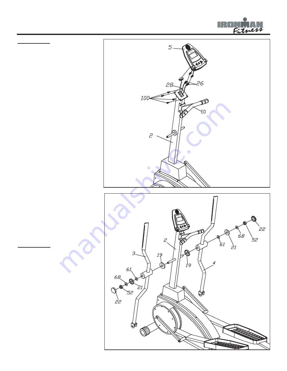
FIGURE 5
Step 1:
Connect Cables as shown.
Note: Be careful not to pinch
wires. Excess wire should
be pushed back into Main
Upright.
Step 2:
Attach Console (5) to Main
Upright using four Screws
(59).
Note: The four Screws(59)
will already be installed into
the back of Console (5) when
you remove it from the box.
Step 3:
Attach Reading Rack by
inserting into holes located on
the console.
Step 4:
Remove protective over-
lay screen from the console
screen.
Figure 5
Figure 6
FIGURE 6
Step 1:
Attach Left Handlebar (3)
using Spacer (19), Washer
(61), Washer (68), Cap (21),
Nut (52) and Cap (22).
Step 2:
Repeat for Right Handlebar
(4).
Summary of Contents for 530e
Page 20: ...Exploded View 20 ...


