2A
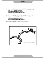
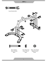
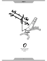
. Remove twist ties From Main Frame (A), but leave the two Bushing (270)
parts in place.
2B.
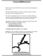
loosen the Ball Knob Pop Pin (102) on the Main Frame (A) to allow for
the insertion of the Seat Adjustment Arc (F).
2C
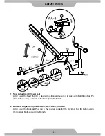
. Insert the Seat Adjustment Arc (F) into the slot on the Main Frame (A)
and secure it in place by inserting it into one of the holes of Seat Adjustment
Arc (F) and tighten the Ball Knob Pop Pin (102), as shown in Fig AA-2
2D
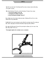
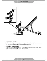
. Attach Seat Plate (E) and Backrest Frame (D) to the Main Frame (A) by
aligning all the holes of the three parts by using:
1 - (10) Hex Bolt M12x1.75x125L
1 - (76) Nylon Nut M12x1.75x12T
2 - (52) Flat Washer D24xD13.5x2.5T
Thoroughly tighten the hardware once complete
WARNING: Do not over tighten the Hex Bolt (10) and Nylon Nut (76); doing so
may make changing the Seat and Backrest angle positions difficult.
STEP
2
14
Summary of Contents for 6871.1-122915
Page 2: ......
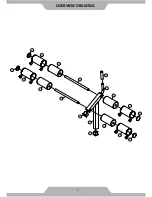
Page 8: ...OVERVIEW DRAWING 6 ...
Page 9: ...7 OVERVIEW DRAWING ...
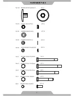
Page 10: ...HARDWARE PACK 8 ...
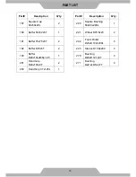
Page 13: ...11 ...
Page 27: ...STEP 7 25 NO 120 Round Cap D25 4xD65x31 5 4PCS ...


