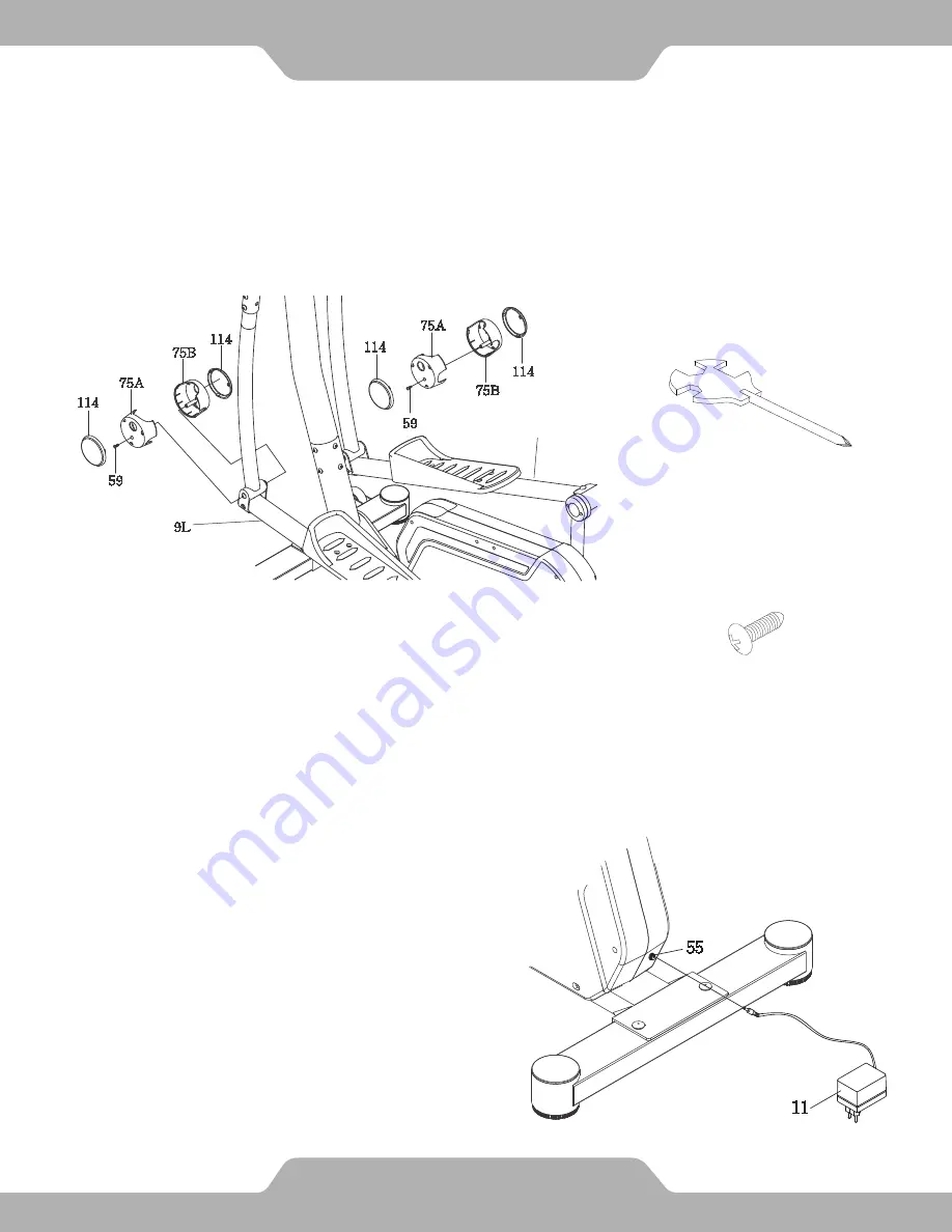
14. Adaptor Installation.
13. Assemble Foot Bar Covers A/B.
Place the Foot Bar Covers-A/B (75A, 75B) around the Left/Right Foot Bars (9L, 9R).
Tighten them with two Round Head Self Tapping
Screws (59) by using the Multi Hex Tool with Phillips Screwdriver until firm and secure.
Attach four Plastic End Caps (114) onto the Foot Bar Covers-A/B (75A, 75B).
Hardware:
(#59) Round Head Self
Tapping Screw
2 PCS
Tool:
Multi Hex Tool with
Phillips Screwdriver
ASSEMBLY
Plug one end of the Adaptor (11) into the
power jack of the Power Supply Cable
(55) on the back of the Right Cover (21R).
Before plugging in, make sure to check
carefully the specifications on the Adap-
tor. Plug the other end of the Adaptor (11)
into the electrical wall outlet.
22
22
9R
Summary of Contents for H-Class 610
Page 2: ...6336 1 082514 2 ...
Page 7: ...OVERVIEW DRAWING 7 ...
Page 8: ...OVERVIEW DRAWING 8 ...
Page 29: ...55 75 90 100 COMPUTER 29 ...


