Assembly
7
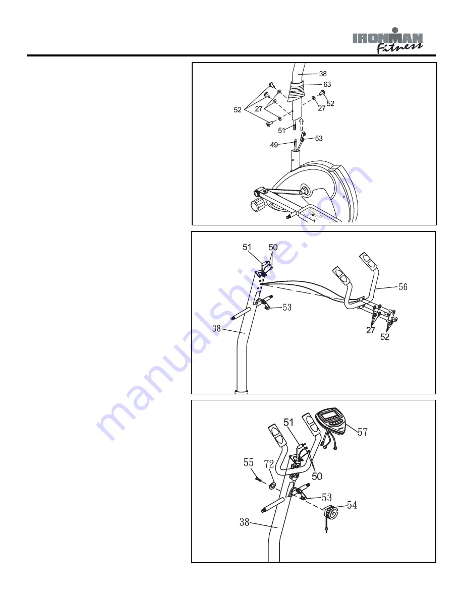
FIGURE 4:
Step 1:
Slide the Plastic Bellows (38) onto the
Upright Post (38).
Step 2:
Connect the Console Cable (51) to Sensor
Wires (49). Slide the Resistance Cable
(53) thru the Upright Post (38) and out
the large hole on the side of the Upright
Post (38).
Step 3:
Using Two Washers (27) and Screws (52),
Attach the Upright Post (38) to the Main
Frame. Slide the Plastic Bellows down
until it meets the Main. Assembly.
FIGURE 5
Step 1:
Insert the Pulse Wires (50) into the bigger
hole on the Upright Post Assembly. Pull
the Pulse Wires out thru the top of the
Upright Post Assembly (38). Using Two
Screws (52) and Arc Washers (27), Attach
the Pulse Handlebar to the Upright Post
Assembly.
FIGURE 6
Step 1:
Connect Tension Knob (54) to Resistance
Cable (53). Refer to Figure 6a,6b,and 6c
for detailed instructions. Using one Screw
(55) and Washer (72), Attach Tension
Knob to Upright Post Assembly (38).
Step 2:
Connect the Console Cables (51) and the
Pulse Cable (50) to wires coming from
Console (57).
Step 3:
Slide the Console (57) onto the Upright
Post Assembly.
Summary of Contents for IRONMAN 120e
Page 14: ...Exploded View 14 ...
Page 15: ...Exploded View 15 ...


